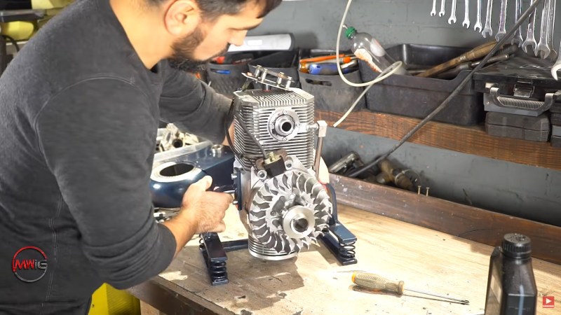
It’s a dedicated hacker who has the patience to build an engine from scratch. And it’s a borderline obsessed hacker who does it twice. [Meanwhile In the Garage] is of the second ilk, and in the video below the break, he takes a failed engine design and musters up the oomph to get it running.
The whole build began with an idea for a different kind of intake and exhaust valve. [Meanwhile In the Garage] dreamed up a design that does away with the traditional poppet valve. Instead of valves that open by being pushed away from their seat by a camshaft, this design uses a cylinder that is scooped so that as it rotates, its ports are exposed to either the intake or the exhaust.

During the compression stroke, the valve cylinder becomes part of the combustion chamber, with both ports facing away from the piston. If you read the comments, you’ll find that multiple people have come up with the idea through the years. With his mill, lathe, and know-how, [Meanwhile In the Garage] made it happen. But not without some trouble.
The first iteration resisted all valiant attempts at getting it started. The hour-long video preceding this one ended up in a no-start. Despite his beautiful machine work and a well thought out design, it wasn’t to be. Fire came from the engine either through the exhaust or the carburetor, but it never ran. In this version, several parts have been re-worked and the effect is immediate! The engine fired up nicely and even seems to rev up pretty well. Being a first-generation prototype, it lacks seals and other fancy parts to keep oil out of the combustion chamber. Normal engine oil has been added to the fuel as a precaution as well. The fact that it smokes quite badly isn’t a surprise and only proves that the design will benefit from another iteration. Isn’t that true for most prototypes, though?
Home-grown engines aren’t a new thing at Hackaday, and one of This Author’s favorite jet turbines used a toilet paper holder. Yes, really. Thanks to [Keith] for the Tip!


Missing diagram of his engine, to compare to provided diagram.
Watch the first minute of his previous video for a clearer explanation of it: https://www.youtube.com/watch?v=u_F5OGjLpOQ
Look on PAT Engine From 1900-1950
Also look on Nimbus Danish Motorcykel
Pat Engine head Rotary valve.
Isn’t this just a version of a 2 stroke?
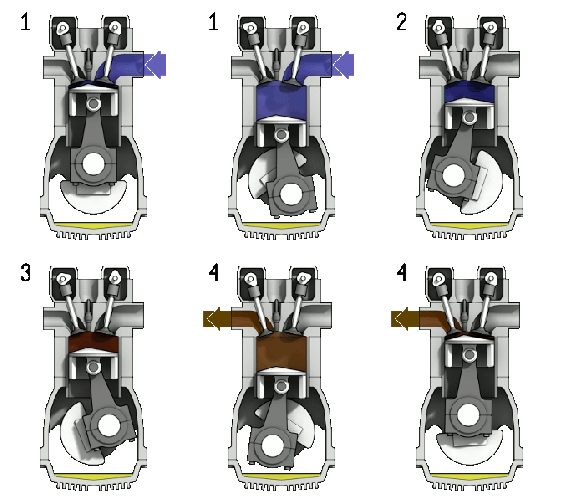
No. If the gif is the engine in question than that clearly shows 4 strokes per ignition
You’re right. The gif does show a 4 stroke engine…not sure where the innovation is in the gif
That’s what I thought as well…
There isn’t really a clear diagram in either the article (which shows a conventional 4t engine) or video but this still works on a 4 stroke concept – an independent valve system with states for inlet open, exhaust open and both closed -but now using ports in a rotating shaft instead of poppet valves. In a two stroke the “valves” are just ports opened by the motion of piston. I think the innovation for this project is in trying to drive the valves directly from the timing belt /cam shaft rotary motion and cut out the cams, springs and linear motion of conventional valves.
Your thinking in the right direction though manipulating a 1:4 to get a modified performance of a two stroke that is where vvt is a really strong idea.
They did this in the 90s with a car engine…..
I researched this in the 60s, I think Norton did this for one year of racing with the Norton Manx. At the time, I had to go to a large library to find a record of the work. According to what I read back then, there was no advantage over the poppet valve design in the 500cc Norton, so it was abandoned.
I tried this with a rotatry cone valve in the early eighties. Mine smoked a bit also. I was able to run it on white gas with great results. Ran out of money, oh well.
Joe winn
I first read that as rotary engine, not valve, and was very confused.
I love the renewed questioning of the standard engine design. Wesley Kagan has been messing around with Koenigsegg’s Freevalve. https://www.youtube.com/watch?v=k_MrPylnsDg
When I saw the first video’s “rotary valve” title, I had some hope that someone had lost their mind and attempted to recreate the clockwork madness that is a rotary sleeve-valve engine. Yes, they ran beautifully and sounded wonderful but…
https://youtu.be/GH2FBuDv_dE
Same! I’d love to see a modern take on one.
They were making this rotary sleeve model aircraft engine into this millennium, but apparently no more. Fairly straightforward at the model level with fewer parts than an overhead valve engine.
https://www.rcgroups.com/forums/showthread.php?567998-RCV-91-CD-Four-Stroke-Rotary-Sleeve-Valve-Engine
One of the really cool things about some rotary sleeve valve engines is they ran the sleeve valves with an epicyclic gear train to get non-uniform motion, so the valve could dwell at not open and then quite suddenly run to fully open and dwell there, and then close quickly. That made timing more precise and gave them a lot of advantages in flow efficiency.
There were several reasons that the largest and most powerful aircraft engines in WWII were mostly rotary sleeve valve.
also makes it possible to supercharge a two-stroke, it is not possible with normal piston ports because the exhaust closes after the intake
Detroit 2 cycles were supercharged
Actually a Detroit 2 stroke will not run without a blower. A gas 2 stroke uses crankcase pressure to force the air/ fuel mixture into the cylinder thru the cylinder wall ports but that’s not an option with the Detroit. It is still basically breathing at atmospheric pressure. There were Detroit’s with turbos getting pressurized air to the blower, and those were technically “supercharged” (air entering the cylinder at higher than atmospheric pressure). So your basic 2 stroke Detroit with just a blower is in fact not supercharged.
Yup – engine hack. Hack, cough, cough. :D
Reminds me of the coates heads:
https://www.youtube.com/watch?v=ijj_E7TXsPE
https://www.youtube.com/watch?v=vjHkAgi9TbY
Agreed. Coates was way ahead with this idea 10-20 years ago.
Unfortunately, Coates burned through a lot of investor money and never produced a practical and reliable system.
Just wondering on your opinions of the coates CRSV engines and there hho reactors they are working on.
If I built an engine like that, and it started, I’d be just as happy. My only lawnmower engine hack was to add a light switch to turn it off after my “safety cable” broke.
That exhaust is rich enough to run another engine off, just inject a bit more oxygen.
An afterburner on a piston engine, driving a blowdown turbine coupled to the crankshart.
You’re well on your way to inventing a jet engine with a kinda weird burner setup.
The P51 mustang had a sort of jet engine running off the main motor. Added a few more mph off waste heat basically!
Turbo compounding. Several radial engines used that in WWII as well
When citing “CC BY-SA 3.0” content, it is not OK to just put “Courtesy of Wikipedia”. You must keep the original attribution, name or pseudonym, of the copyright holder which is not “Wikipedia”.
Please read https://commons.wikimedia.org/wiki/Commons:Credit_line#CC-BY_and_CC-BY-SA_licenses
There were engines years ago that used a rotary disk for a valve and a similar concept. https://en.wikipedia.org/wiki/Rotary_valve The lack of valve motion aids in power and raises RPM limits since there are no springs or valve mass in alternating directions. It also greatly simplifies the engine components with the removal of 2-4 (or more) valves, springs, retainers, dampeners, rockers, lash buckets, pushrods and other parts per cylinder). This reduces the number of moving parts in a 4 cylinder short block engine to 20 or less including the oil and water pump. I had an idea for a rotary valve system that only has 1 port per cylinder and the rotary valve gate would alternate between the intake and exhaust side by grinding the port gate at an angle into the valve rotor and have it sweep over both intake and exhaust manifold joints. It would be good for low RPM, but at high RPM the lack of valve overlap time would affect VE. It would be interesting to build at about 6:1 CR, direct injection, plasma ignition, and run a turbo at about 3-4 bar with boost starting at idle making a high torque low RPM engine. Guessing 1 litre 4 cylinder could make about 200+ HP under these conditions easily, from an engine that could possibly weigh about 40kg and be the size of a large toaster.
It seems to me an obvious flaw will be the build-up of combustion products on the rotating valve. You need to seal the compression around the valve and those compression products will ruin any possibility of sealing for long
Smokey Yunick designed a rotary valve engine 60 years ago. One of the smartest engine builder – designers ever
There have been several rotary valve designs through the years, but poppet valves have continued to reign that whole time. If any of the rotary valve designs were clearly superior, they would have supplanted them.
Coates did this in the States in 80’s. Huge improvements in BHP and Newton’s. Never took off due to machining costs.
Willis jeeps used a rotary valve engine many years ago and was used in production vehicles…… successfully…
For too long we are stuck with old engine design and all we do is try to make them more efficient so I am delighted to see this revision of the internal combustion engine. Quick question, is this format more efficient or powerful than a standard engine. What about its durability and maintenance. It seems more compact.
It’s a beauty to watch it working. All the best
Book From 1965..
Ternai Zoltán..
Write the rotaty valve motor…
Rotary valves were used as far back as the late 1890s. The Argyll experimented with them.
Gotta kick the RPM up, no valve float (valve springs can’t return to closed fast enough), there’s your advantage
If the cam barrel had a 2nd spring loaded and centrifugally controlled concentric internal barrel mechanism to adjust port size and placement the mechanism would allow for variable valve timing and duration according to RPM. (asymmetrical port alignment overlap between the inner and outer barrel). These types of mechanisms can produce volumetric efficiencies in the 130% range through the optimization of valve events. Modern materials allow for about 26.9 M/s max piston speed (F1 and other very high end engines) If an engine has a 2″ stroke and 4″ bore displacing about 25 cu in per cylinder, at 18000 RPM (where the 26.9 m/s speed becomes the limit) and 130% VE each cylinder will consume 170 CFM or enough air to produce 245 HP per cylinder. In an engine with no possibility of valve bounce the only other limiting factors are parts and assembly stress failure limits, ability to maintain sufficient oil film on the friction surfaces, and ability to cool the parts.