Thermoacoustic Stirling Engine Is Now Fully 3D Printable

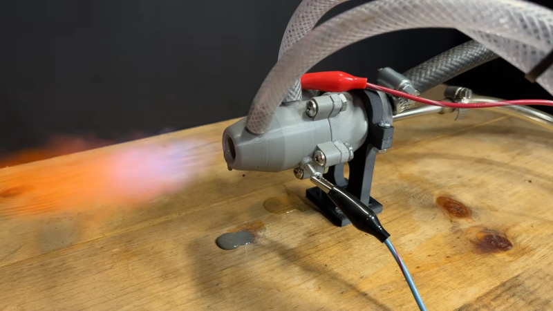
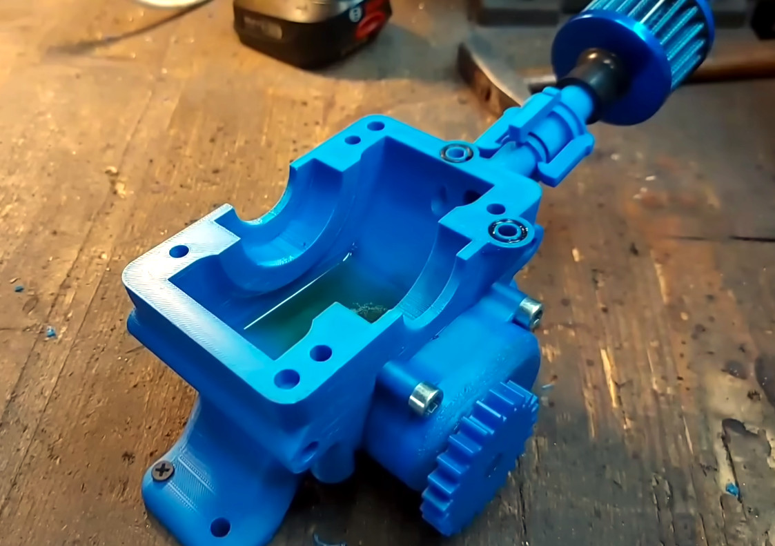
Would you like to make your own energy? Why, who doesn’t in this era of rising costs! A Stirling engine always looks like a good fit for that: highly efficient, with no risk of a boiler explosion. A thermoacoustic Stirling engine looks even better, since it has only one moving part at the output end. A thermoacoustic Stirling engine you can 3D print yourself looks best of all, and that’s what [my engines] has on offer, now that even the burner and hot end of his thermoacoustic engine are designed for SLA metal printing.

We previously reported on the open-source engine, but there’ve been some improvements worth talking about. For one thing, he’s integrated a biogas/methane burner directly inside the 3D-printable hotend. For another, that 3D-printed design allows for an excellent heat exchange geometry that would be very hard to get any other way. The whole thing is open source with plans available at OwnEnergy.org, where you can find links to the apparently mandatory Discord channel and now an old-style forum to actually collaborate on the design, which is open-source. The site is also now the home of all data and discussion about [my engines]’s homescale biogas plant, which is the power source for this little engine.

If you’d rather print a combustion engine, you can do that, too, but you’ll need more “vitamins” than this unit requires.

Continue reading “Thermoacoustic Stirling Engine Is Now Fully 3D Printable”

Historical Hack: Henri Giffard’s Steam Injectors

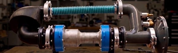
Here’s a historical hack for you: you have a big, rolling pressurized kettle, also known as a steam locomotive. It needs water to make up for the steam constantly chuff-chuff-chuffing away, or bad things happen. How do you get water from an unpressurized tender into a high pressure boiler with no moving parts? What you need is a some way to inject steam with no moving parts — a steam injector, if you will. [Marc Flint] found that the steam injectors were the hardest part of a loco to understand, so he made a video for all of us once he’d figured it out.

The steam injector isn’t a new idea. [Henri Giffard] came up with it back in the 1850s to replace expensive and maintenance-hungry pumps. It’s rather ingenious and uses the fluid mechanics uncovered by another European bloke by the name of Bernoulli. First, the high-pressure steam from the boiler goes through a converging-diverging nozzle to drop its pressure and speed its flow up, just as you’d guess if you’ve seen Bernoulli’s laws. Even more vacuum-inducing is the presence of water: the steam, already cooled by its expansion, hits the water in the pipe open to the tender, and condenses into it, shrinking a couple of orders of magnitude, creating a vacuum that draws in no small quantity of feed water. That one we did not expect from Bernoulli, but it makes sense. So how to get from below atmospheric pressure to the 180-odd PSI or more in the boiler?

Well, the water is now moving at a good clip, between the Venturi effect and the momentum gained from absorbing that steam, so another converging nozzle is the trick. Bernoulli’s law, once more! A one-way valve lets the now-pressurized water into the boiler, with a gap in between to dump water while the pressure builds up. It’s a clever trick, and since the steam coming from the boiler makes it back inside along with at least some of its heat energy, it’s much more efficient in both coal and water than running a pump. It’s also a bit of a head scratcher how it works unless someone sits you down to explain it, so we’re glad [Marc] did.

Not many of us are likely to use this knowledge directly — unless we’re firing up a 90 year old boiler or building a new steam locomotive — but seeing how great engineers of years past made use of basic physical laws can serve both as education and inspiration.

Continue reading “Historical Hack: Henri Giffard’s Steam Injectors”

Water-cooling A 3D Printed Rocket Isn’t Quite Practical

Consumer-grade 3D printers are useful for lots of things, but they kind of fall down when it comes to making stuff that survives high temperatures. [Mr. More Gooder] wasn’t deterred from a rocket build using FDM printed parts though, instead relying on water cooling to try and beat this practical limit.

The concept is simple enough—[Mr. More Gooder] printed a propane-burning combustion chamber and nozzle out of plastic that you’d totally expect to melt when the flames started. Thus, the nozzle was given fittings to allow water to be continually pumped through to try and drag away enough heat to let the rocket survive more than a few seconds. Unfortunately, during testing the uncooled combustion chamber quickly melted. A redesign with water cooling throughout performed a little better, until the water jacket began to leak into the main chamber and extinguished the flames. Melted plastic could be seen dripping out of the nozzle shortly after ignition, too.

Even if the nozzle did hold up for a longer period of time, it’s worth noting this is probably not a viable route towards a flight-ready engine. Mostly because you would need a huge supply of water to keep the components cool which would add a great deal of weight to any such build. There’s a reason NASA doesn’t recycle old drink bottles to make rocket engines, after all.

In any case, we love to see all sorts of rocket experiments, even the unsuccessful ones.

Continue reading “Water-cooling A 3D Printed Rocket Isn’t Quite Practical”

Small Engine Gets DIY EFI Upgrade

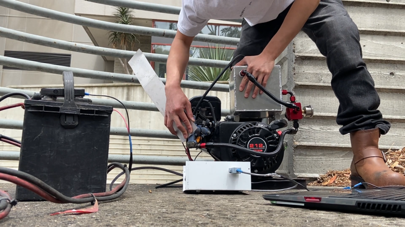
Small internal combustion engines usually keep things simple, relying on carburetors to handle metering the correct amount of fuel and air. Recently, [Carlos Takeshita] decided his small engine could use an upgrade in the form of electronic fuel injection (EFI).

The build began with a Predator 212, a popular gasoline engine from Harbor Freight. [Carlos] set about kitting it out with a missing tooth trigger wheel to measure the crankshaft position with a hall effect sensor. The engine also scored a custom-built aluminium fuel cell, complete with a high-pressure fuel pump and regulator suitable for driving the solitary fuel injector installed in the custom intake manifold. A Teensy 4.0 is charged with monitoring a manifold air pressure (MAP) sensor and the crank position, and choosing when and how long to fire the injector to dose the engine with the correct amount of fuel. Files are on GitHub for those eager to dive deeper.

It can be quite a job to convert an engine to run with electronic fuel injection, but you’re certain to learn a lot during the install and tuning process. We’ve featured similar builds many times over the years.

Continue reading “Small Engine Gets DIY EFI Upgrade”

Machining A Two-Stroke Engine Out Of Aluminium

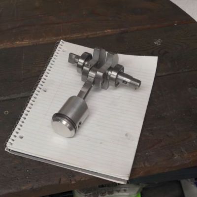
Recently [Camden Bowen] took a swing at machining a two-stroke engine out of billet aluminium, following adventures in 3D printing such an engine, as well as building one out of parts largely sourced from a hardware store. The sketchiest part here is probably the use of only a basic mill and lathe, making the milling of certain shapes a definite OSHA violation.

Two-stroke internal combustion engines are pretty simple from a mechanical point of view, with designs readily available. Add in a suitable material to machine and a modicum of machining and welding skills, and presto, you got yourself a not too shabby looking engine.

Of course, back in reality things are a bit more hairy. Not only are there many different ways to produce the parts – with some coming with a time penalty, monetary penalty, or both – but there are also myriad ways to hurt yourself and/or others. Fortunately [Camden] scraped by with just some (expensive) lessons learned and a major ruined part.

The final design features a single cylinder, with an initial pressure test showing a solid 150 PSI (10 bar) of compression. With that encouraging sign, a coil pack and contactor were added for some spark and a test run with the usual premixed gasoline-oil fuel.

Boringly, the engine mostly just runs and work as it should. This is of course not unexpected, much like how following the recipe for a pie produces said pie. But it does demonstrate how easy things are when you do not stray off the beaten path. The only significant issue was the flywheel wobbling slightly, likely due to a small manufacturing glitch, but this should not cause too many issues.

Continue reading “Machining A Two-Stroke Engine Out Of Aluminium”

You Wouldn’t Download A Combustion Engine

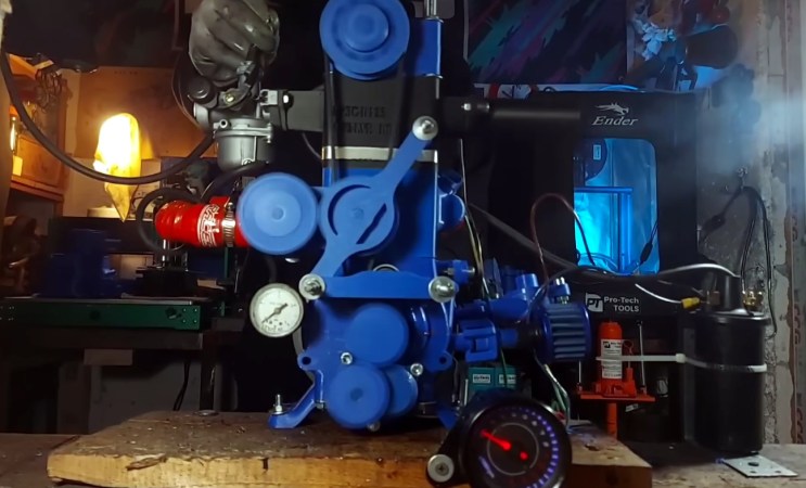
Although 3D printing it a great tool for making all sorts of things, the nature of the plastics used in most desktop FDM printers means it isn’t the first tool most would think of to build an internal combustion engine. [Alexander] is evidently not most people, as he’s on his third generation 3D printed engine.

There are 3D printed pumps to distribute coolant water and oil, plus some clever engineering in the head to make sure they don’t mix — a problem with a previous iteration. As you probably guessed, the engine isn’t fully printed. Assembling it requires add-on hardware for things like bearings, belts, and filters.

But it’s still impressive just how much of this beast is actually made of plastic. Not even fancy engineering plastic, either — there are a few CF-Nylon parts, but most of it is apparently good old ASA and ABS.

If you’re looking for “cheats”, the plastic engine block does get a stainless steel sleeve, and the head is CNC’d aluminum, but we hesitate to call anything that gets a homemade engine running a “cheat”. It’s hard enough using all the ‘right’ materials. Just like another 3D printed engine we featured, the carb is also an off-the-shelf component.

Still, it’s the dancing bear all over again: it’s not how well it runs that impresses, but the fact that it runs at all. We’ve also seen hackers use 3D printing to make steam engines, hot-air Stirling engines, and electric motors— all with varying amounts of non-printed parts.

Continue reading “You Wouldn’t Download A Combustion Engine”

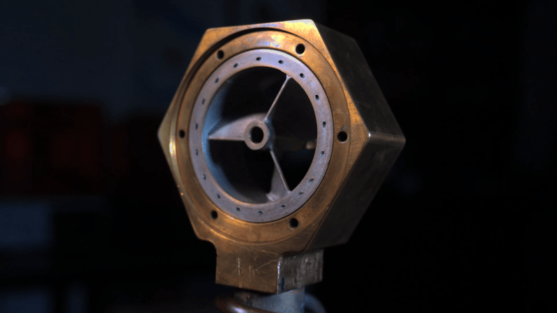
A hexagonal brass enclosure surrounds an aluminium fan with three blades. The fan has an integrated outer rim with a series of small holes around the rim.

Building A Rim-Driven Jet Engine

Rim-driven thrusters turn the normal propeller-motor arrangement inside out; rather than mounting the motor at the center of the propeller, they use a large hollow motor, with the blades attached to the inside of the rotor. They’re mostly used in ship propellers, though there have been some suggestions to use them in electric aircraft. [Integza], always looking for new and unusual ways to create propulsion, took this idea and made it into a jet engine.

Rather than using an electric motor, the fan in this design is propelled by miniature rocket nozzles along the edge. The fan levitates on a layer of high-pressure gas between the fan rim and the housing. To prevent too much pressurized gas from escaping, the fan and housing needed to fit together closely, but with minimal friction. A prototype made out of acrylic and resin and powered by compressed air proved that the idea worked, but [Integza] wanted to make to this a combustion-powered engine.

Continue reading “Building A Rim-Driven Jet Engine”