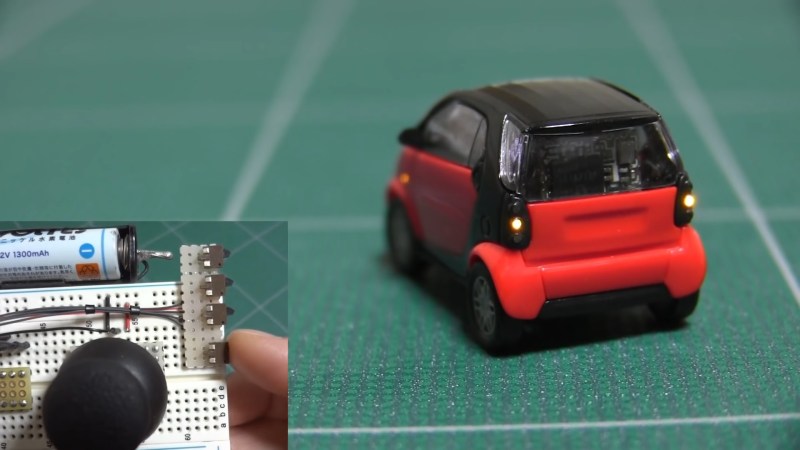
Small is often subjective. For example, a school bus is small compared to an Airbus A380. But other things are just small all on their own and need no comparison to make the point. Such is the case with this micro RC car in the video below the break. It’s an RC model of the Smart Car, that when compared to other vehicles on the road, is quite diminutive, both subjectively and absolutely. But the outward appearance of [diorama111]’s project only tells half the story.
Starting out as a static display model, [diorama111] fully disassembled the 1/87 scale Smart Car and got to work. Fully proportional steering is attained with a very, very small stepper motor that drives custom knuckles attached to handmade suspension. They are works of art in their own right.

Drive is supplied by another small stepper motor. If [diorama111] had stopped there, it would have been every bit as noteworthy to see a 1/87 Smart Car doing figure eights around small bottles of model paint. Instead, [diorama111] kept going! The car has working turn signals, brake lights (including the 3rd taillight in the back window!) and headlights. There is even a function for hazard lights.
The electronics are all hand built using enameled wire and SMD components on perf board, and are a study in miniaturization all their own. An ATtiny processor seems right at home in this design. We admire [diorama111]s steady hands and patience to build such a small RC car, never mind one with such fine attention paid to all the details.
If downsized hacks like this float your thimble-sized boat, you might also appreciate this precious little PDP-11 and terminal.
Thanks to [furby73] for the great tip!


WOW!
Amazing work, it’s incredible how small things can be made these days. Awesome that you included every detail into the build video 😀
What a great build!!! Thorough down to the tiniest detail!
Such a beautiful piece of art. Thank you for this.
+1
I don’t want this to come off wrong absolutely amazing on the build and the thought that went into this.
I have only one question why a motor for steering and not just a linear servo?
A servo would require the addition of a potentiometer and an analog input to read it. This way, it requires fewer parts, less room, and since it’s a stepper motor, just some calibration to center the steering, which it would need anyway.
Looking more closely at the documentation, I see that he used an optical end-stop to determine when the steering reaches the right limit. This doesn’t seem to be shown in the video.
He probably could have put a resistor in the ground circuit of the bipolar motor diver and monitor voltage increases when it get to the end of travel and us that to CAL center.
Holy cow, that’s some amazing work.
nice work! it needs a horn ! there must be some room left for a tiny piezo resonator, no?
Steppers can be speakers… Full function stereo? :o)
Good point. The stepper already seems a bit loud. You can hear that it appears to take big steps steering in one direction and be smooth in the other.
So yeah, just a bit of extra code and you would have a faint buy audible horn.
Stereo might be a bit tricky. The steering is a bipolar stepper and the rear wheels have a brushed DC motor.
As far as control, looks like he could operate the horn from the programming port.
Very cool. It seems like an odd choice to forego making a custom PCB considering it could both reduce the size and act as a structural component.
Possibly. But it would also need to have a lot of layers otherwise he wouldn’t be able to pack the components so densely. 4 layers could not be enough to run all those signals – and then it gets into a very specialist territory (= expensive). With the flying wires he can have as many “layers” as he wants because he doesn’t need to worry about crossing tracks.
A more logical thing would be to forgo the separate Bluetooth module and microcontroller but to use an MCU that has a built-in radio – e.g. a module with one of the nRF52 chips. Those can be had in very tiny sizes. On the other hand the programming is a lot more complex and it is Bluetooth Low Energy, not Classic …
I was amazed when I saw that the control arms with within the internal diameter of the wheel.
In every scene i can see what i would have done.
Would have tweaked that metal plate into a pretzel chip,
Lost that tiny part twice.
Numerous punctures in my fretting fingers
And sweep the whole thing on the floor with my sleeve cuff.
Twice at least.
Bravo!
Eh, i like coffee too much.
For me the last step would have been an emotional loss of patience involving a hammer and an anvil.
Car’s keep getting smaller all the time, how am I supposed to get groceries into this!?
A pea at a time :)
Love the ‘dead bug’ wiring. I try to pass those types of tribal knowledge on to younger engineers nowadays before I retire.
Me to but I can’t compete with this. He has more magnet wire there than I have hair, and that’s even before I start.
I still think it needs a tiny little horn.
This is incredible. I’m impressed that even the lights were made functional. It’s amazing how small things have gotten these days.
Yep, same guy who did the 1/150 scale RC car a year ago. But that was a Toyota Crown, so much bigger than a Smart. But he outdid himself with the lighting on this one.
Very, very nice!
But there is still room for improvement: he could use 01005 resistor/capacitor chips and XFBGA/UFBGA/WLCSP microcontrollers/ICs with 0.4mm PCB thickness and 3.5mil trace with, 3.5mil clearance and 0.2mm drill holes ;-)
That would be the current technology limit!
BTW, where can you find these little stepper motors?
From the lenses of digital point and shoot cameras, I guess? Lovely little car indeed!
Would love a parts list / BOM. Which lead screw and stepper? What about that little plastic worm gear? Super cool project!
Only miss a honk loll
This is just the one they tell us about. I heard there’s an even smaller one driving around inside Supermicro motherboards as we speak.
Very nice build! Also perfect for office desk races.
…and my cat wants one too.
Where’s the video gone?