One may think that when it comes to 3D printing, slicing software is pretty much a solved problem. Take a 3D model, slice it into flat layers equal to layer height, and make a toolpath so the nozzle can create those layers one at a time. However, as 3D printing becomes more complex and capable, this “flat planar slicing” approach will eventually become a limitation because a series of flat slices won’t necessarily the best way to treat all objects (nor all materials or toolheads, for that matter.)
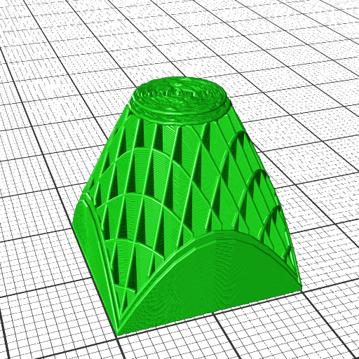
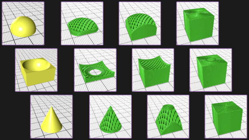
[René K. Müller] works to re-imagine slicing itself, and shows off the results of slicing 3D models using non-planar geometries. There are loads of pictures of a 20 mm cube being sliced with a variety of different geometries, so be sure to give it a look. There’s a video embedded below the page break that covers the main points.
It’s all forward-thinking stuff, and [René] certainly makes some compelling points in favor of a need for universal slicing; a system capable of handling any geometry, with the freedom to process along any path or direction. This is a concept that raises other interesting questions, too. For example, when slicing a 20 mm cube with non-planar geometries, the resulting slices often look strange. What’s the best way to create a toolpath for such a slice? After all, some slicing geometries are clearly better for the object, but can’t be accommodated by normal hot ends (that’s where a rotating, tilted nozzle comes in.)
Such worries may not be an issue for most users at the moment, but it’s worth trying to get ahead of the curve on something like this. And lest anyone think that non-planar slicing has no practical purpose, we previously covered [René]’s demonstration of how non-planar slicing can reliably create 90° overhangs with no supports.


So, the thing is that it’s relatively, sort of, vaguely, easy to figure out that kind of slicing… until you have to think about whether the tool head is going to hit any parts of any reasonably complex object when you actually build it. Especially if that object is not entirely convex. Tilting the nozzle won’t solve all the cases and will further complicate the cases that it does not solve.
… andonce you’re thinking about non-planar toolpaths, it’s not immediately obvious that “slicing” is the right way to approach the problem at all. I mean, yeah, there will always be an accessible part surface and in some sense you can say you’ve “sliced” along that, but given that that surface can evolve arbitrarily during the print, it’s not at all clear that the conceptual framework gets you anywhere.
Anyhow, however you do it, at a wild guess, I’d say that going non-planar for arbitrary shapes probably multiplies the raw computing power required by a million, as well as making the software vastly more complicated.
So the improvement had better be *radical*.
Not to say that you can’t do it for special cases. But you can also hand-craft the G-code for those cases…
I mean, it’s “just” the same class of problem as finding the optimal path for a robot arm e.g. for assembly lines.
So, a darn hard class and we’re into the decades of high-profile academic and industry research and haven’t found an optimal way yet, but a few nice heuristics and a few optimal solutions for *very* specific special case problems.
The computing power required to generate the toolpaths really doesn’t much matter anymore – nothing this sort of slicing is doing will really make you wait much longer even on a very slow computer, at least while it is only dumb alternative slicing – you tell it cone with 20 degree slope it slices in that slope, as that is all simple trigonometry co-ordinate translation really. Even adding in a rotating print head/build plate to allow for greater access around parts and steeper slopes doesn’t add much extra complexity in terms of compute time while it remains ‘dumb’, with the only slicing limitation being to avoid tool collisions – so lots of overhangs and bridge over the areas the head won’t get into following the slicing shape instruction…
The real increase in computing time will be if its trying to parse the geometry and consider possible print angles and slice methods for best surface finish/ most uniform strength etc automatically – suddenly you have to consider every possible plane through every possible point on the model and decide which shape to slice with at each point within the clearance limitations of the hot end, and mechanical stresses of the part.
The real question I have is does FDM have enough future such that this style of slicing complete with structural analysis and surface finish ironing options makes sense to develop? – The UV cure resins are not as ecologically sound (IMO anyway), and certainly still have mechanical limitations compared to FDM’s wider range, though good mechanical options do seem to be becoming more available. For me though its the sintered powder printers, that are getting cheaper and more accessible and they have the full scope of materials available for your task, superb detail is possible and there isn’t a hugely significant structural effect of the layers in printing.
For myself I think FDM is going to remain for as long as we use thermoplastics if decent and effective plastic recycling to filament or print straight from shredded plastic printers improve, as its just so versatile, cheap and importantly the materials are easily recycled at least a few times then (as thermal cycle degradation may need to be considered)… With the added very useful ability to make something really pretty decent from just a tiny bit more material than you actually need for the item (perhaps some supports, and the little bit between the extruder drive wheels and print head) makes for great printing experience – resin and powder you must have enough materials to fill the entire layer so need to keep in stock lots of material you won’t actually ‘use’, and they are much harder to work safely with, really bad extra fine dust powders and more nasty volatile organic resin smells…
Not really hard to add in dimensions of hotend to rotation point of hotend and work that into the code. It’s already done with auto bed leveling.
Collision detection is relatively easy. The hard part is planning a correct tool path that doesnt cause collisions. This is almost completely absent with planar slicing.
I’m pretty sure the problem has no optimal solution in the generall case at all. But hand writing g-code is also not very fun, once you have a little more complicated geometry. There has to be a middle ground.
Game changer. Advanced concepts for nozzle extrusion.
When do we get 5 axis fdm?
You could make one today. It’s really the slicing that’s the hard part.
https://all3dp.com/4/open-source-5-axis-prusa-upgrade/
You can buy robot arms, of the shelf. KUKA is typically what people think of when you say “5-axis arm with a tool at its end”, and multiple things, especially the “extrusion” tooling mention (but also things like aluminium welding) in this list would fit “FDM”; in other words: yeah, you can buy this off-the shelf for an industrial use case.
https://www.kuka.com/en-de/products/process-technologies
But I’m pretty confident there’s established players in the field of professional 3D printing that give you more axes of freedom than your average X/Y/Z axis desktop prosumer printer.
Maybe adding space filling curves (like Hilbert’s version) would prevent the jumps in the layers we see. Ideally, each move should be useful for the part.
Part of me is nervous this whole area is a patent minefield… I feel like I heard somebody say there’s at least one patent out there in the realm. Sigh…
Most patents can be disputed & most printers come from China, i doubt we have to worry much about this becoming an issue
I don’t want to sound hurtful, but you sound like you’re inclined to say:
> “How to figure out a path for my 5-axis arm to deposit material” is definitely not something that companies that build industrial welding robots would patent – and even if they did every patent can be disputed, without any respect to the merit of the actual invention, which might have taken decades of R&D.
There’s much wrong about the patent system. Protecting someone who has a good solution to this *extremely* hard problem and still decides to put it out in the public isn’t what’s wrong.
So, for the heck of it, I know Autodesk has (already public) patent applications especially in the field of covering a planar 3D print with non-planar layers, and I know of at least one application that was abandoned, and looks like a competitor patented prior art.
Seriously, this is a thing where you can sink *serious* R&D cost and there’s *serious* money to be made by your competitors – finding methods to do nicely printable non-planar slicing and toolpath generation would clearly be a prime candidate for patenting. There’s bound to be dozens of patents :) And I don’t even think that’s a bad thing! This might be the patenting system being *productively* at work.
Patents are usually restricted to only the territory(ies) where they are applied. And they can be broken if there’s interest for that, already seen some governments doing that to patents of medical drugs.
Um, one of the moral criticism against western governments in this epidemic is that they actually did *not* just do that, but chose to uphold the IP system rather than giving access to industries in threshold countries.
Why on earth would a government repeal a patent on such a technology? “Because I want it to appear in a 200€ printer” is not a valid reason to make exceptions to the rule of law, usually.
You are thinking about 3d printers, but patents are much broader than that. In fact I was referring to medical drugs patents, but didn’t explicitly mentioned it to keep the conversation on topic.
On the other hand, everything is a patent mine field these days. Once you get big enough to be profitable to sue, someone will find a patent you violate.
The “cone shaped plane” made by brain halt until there was a hunger interrupt.
The most underdeveloped area of the entire software chain is the use of multiple materials/extruders at once.
As in printing at the same time? That has all kind of collision issues.
As in printing multiple materials in the same print but after each other? I implemented that in cura more then 5 years ago
I want my printer slicer software to do both.
Even minor non-planer layers would be a big benefit to general purpose prints: without uninterrupted linear shear lines effective part strength will be greatly increased. High-frequency dimpled/waffled layers would be both near optimum effectiveness in interrupting crack propagation, and one of the more trivial cases to guarantee avoiding nozzle impacts for arbitrary part geometry (set waffle slant angle to be greater than the nozzle cone angle plus some small margin).
Likely one of the trickier problems would be part adhesion: starting parts already ‘sliced’ with the alternate layer geometry as in the OP example invites issues with small initial surface contact layers having to be merged later in the part without dislodging. It may be preferable to start with a planar base layer and slowly morph the layer geometry to the desired warp.
And here we have a recreation of the classic “optimum path” problem, originally put forth to find the optimum route for a vendor to visit multiple customers in a sales district. IIRC, that was found to be unsolvable (other than brute force, check every possibility) but very, very good solutions could be found.
This problem is exponentially worse, since you are dealing in 3 dimensions instead of two, and the paths are almost never straight lines.
Indeed, and what your priority is changes the optimum path too – if you really must have that thin part be extra strong then the layers have to run parralel to it, if surface finish (perhaps with an ironing pass) is the most important than that same feature might well be printed in a very weak layer orientation to avoid needing support material and sagging bridges.
With that last point I really can’t see any algorithm to solve a best fit ‘universally’ the way the traveling salesman problem can be solved – the best you can get is the user blocks out the desired layer directions in advance and the slicer gets as close to that as possible.
Perhaps the much vaunted, but often overrated, machine learning techniques could ‘guess’ what the user will want correctly much of the time, but its never going to be right every time, and when its wrong ML tends to be very very very wrong indeed – which means human inspection of the toolpaths before they get run every time, at which point why not use the human’s own understanding to optimise the layer directions – they actually know what the part is for!
Instead of moving the z axis over the entire top skin, wouldn’t it be more efficient to only do it on a layer-to-the-next basis? LIke, when printing a dome top wall, print circles changing the Z form current-1 to current layer, print vertical walls and infills as usual, then continue to next layer. I can see many problems cominq up of course, but the slicing is probably simpler and the problems of the hot head parts bumping on the print is automatically solved…