If you’ve ever debugged a misbehaving I2C circuit, you probably know how frustrating it can be. Thankfully [Jim] over at Hackaday.io, has a proto-boardable circuit that can help!
Inter-integrated circuit bus (aka I2C) uses open collector outputs on a two wire interface. Open collector means a device connected to the I2C bus can only pull the bus down to ground. Chips never drive a logic “HIGH” on the wires. When nothing is driving the lines low, a weak resistor pulls the lines up to VCC. This is a good thing, because I2C is also a multidrop bus — meaning many devices can be connected to the bus at the time. Without open collector outputs, one chip could drive a high, while another drives a low – which would create a short circuit, possibly damaging both devices.
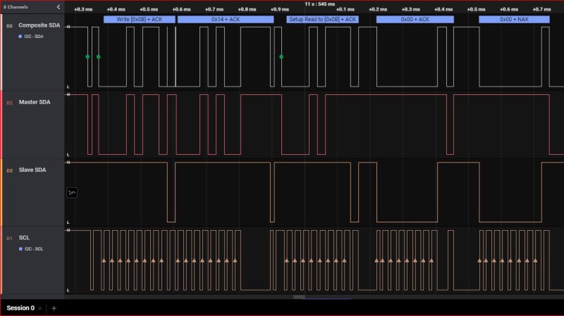
Even with all this protection, there can be problems. The SCL and SDA lines in the I2C communication protocol are bidirectional, which means either a controller or a peripheral can pull it low. Sometimes, when tracing I2C communications you’ll need to figure out which part is holding the line low. With many devices sharing the same bus, that can become nigh-impossible. Some folks have tricks with resistors and analog sampling, but the tried and true method of de-soldering and physically lifting chip pins off the bus often comes into play.
[Jim’s] circuit splits SDA signal into controller-side and peripheral-side, helping you make it clear who is to blame for hiccups and stray noise. To do that, he’s using 6N137 optoisolators and LMV393 comparators. [Jim] shared a NapkinCAD schematic with us, meant to be replicate-able in times of dire need. With this design, you can split your I2C bus into four separate channels – controller-side SDA, peripheral-side SDA, combined SDA and SCL. 4 Channels might be a lot for a scope, but this is no problem for today’s cheap logic analyzers.
The circuit is rated for 100KHz debugging, but if it doesn’t work for your 400KHz (or higher) bus, you can always lower the speed. This kind of monitor is useful for taming devices going rogue, and it isn’t technically limited to SDA splitting! I2C also has a feature called clock stretching, where peripherals are are allowed to manipulate the SCL line, too. In case of clock stretching-related problems, you can swap the SCL and SDA lines, which will allow you to use [Jim’s] circuit on SCL.
It absolutely wouldn’t be hard to assemble a device like this when you’re really stuck with a tricky I2C situation. What kind? We’ve talked about all the possible I2C problems in a long-form article of ours!


Pffff [Jim]. I don’t like suggesting to use a cheap clone with saleae software.
PulseView is open source and more than enough to get the task done. It works out of the box with those CY7C68013A boxes.
What’s wrong with it? It’s a preference, the cheap logic analysers work with it out of the box too. I find it very useful and easy to use, so what’s the issue? If the creator of the software had much of a problem with it they would find a way to make it only work with their own devices.
Piracy hardly just a preference. Saleae doesn’t like seeing their software used with devices that aren’t theirs, and there are measures in the software so that it doesn’t work with chips that aren’t programmed with their tag, so the next anti piracy step would be unique serialised hardware tags and forced online activation. Do you advocate for that, inconveniencing their genuine customers? The clones will just come with cracked versions of the software then…
“Some folks have tricks with resistors and analog sampling, but the tried and true method of de-soldering and physically lifting chip pins off the bus often comes into play.”
That’s my go-to method for any moderate-speed bidirectional protocol. Just stick a small resistor in front of one of the devices. The difference in the “low” level driven by one or the other should be clearly visible on an oscilloscope. One of the commenters on the .io page mentions this method as well.
As for the pin lifting, both solutions require you to insert something between two i2c devices. If you happen to have a nice port on the board, you can just stick the resistor there, no pin lifting needed.
s/open collector/open drain/g
The overwhelmingly vast majority of I2C devices use N-channel MOSFETs rather than BJTs to drive the I2C lines.
As long as it’s not an open sewer it’s ok with me.
Thank-you. I have only just figured out from your comment why “open collector” and “open drain” are the same thing.
A couple of diodes makes it easy to see which end is pulling down. See this example of monitoring the SCL clock stretching
https://www.i2cchip.com/pdfs/I2C_Clock_Stretch_Probe.pdf