The quality of any measurement can only be as good as the instrument used to gather it, and for acoustic measurements, finding a good enough instrument can be surprisingly difficult. Commonly available microphones can be of good quality, but since they are invariably designed for speech or music, they need not have the flat or wide enough response and low noise figure demanded of an instrumentation microphone.
Microphones for measurement purposes can be had for a very large outlay, but here’s [Peter Riccardi] with a unit designed around an array of MEMS capsules that delivers comparable performance for a fraction of the cost.

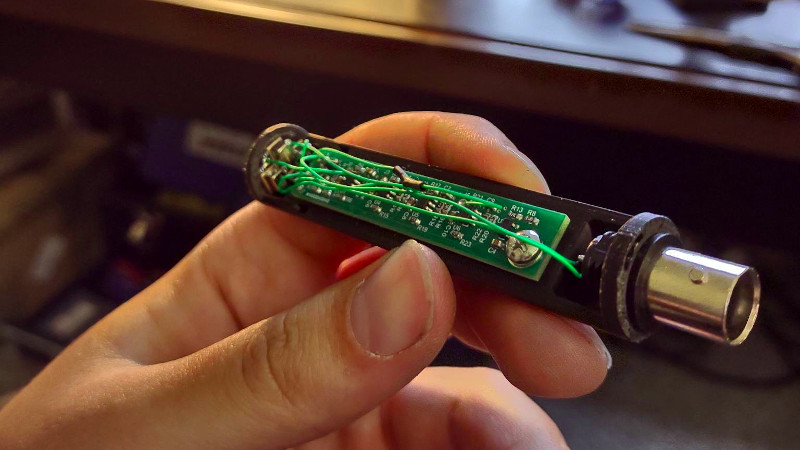
The result is both an extremely interesting project for those of us with an interest in audio, and a thorough delve into some aspects of its design for those who are merely curious. It uses four capsules in an effort to cancel out induced electrical noise, and boasts some impressive comparative measurements when tested against a commercial measurement microphone. We could almost see ourselves building this project.
Interested in audio technology? Try our Know Audio series.


Reading the write up, Its a fairly impressive project but looking at the board and implementation it seems to not take into the affects of proper shielding and signal integrity which could likely boost the performance for very little additional cost for a “Lab-Grade” device. Although the measurements are in the VLF range, I’m sure spurious high frequencies RF that pervade our world can add noise fairly easily to this design. The wiring can definitely be greatly improved, along with the no shielding. Due to the loose wiring, I’m sure its picking up fairly egregious 60Hz noise as well as other high frequencies due to the large loop impedance between the diff lines from the mic, essentially acting as a loop antenna. An easy fix would be to use smaller twisted magnet wire inside a braided metal shield. Also, simply having a metal shell around the entire assembly would do wonders, simply wrap it with foil tape and have a wire connected to GND on the PCB. I might also be talking from my ass as I’m not near as familiar with low frequency, but I always cringe when I see these impressive projects geared towards high fidelity measurements not take into account proper grounding/shielding that’s super easy to implement as well as SI that likely greatly reduce the overall potential the circuits could theoretically achieve.
Hello! This is a really good comment – and you raise excellent points. This is what I’m deeming a “mark 1” prototype. It was the minimal viable product necessary to enter this into a competition – and at the time I was a full time graduate student. The ultimate goal is to build a single rigid-flex PCB and include RF shielding in the enclosure. It simply wasn’t necessary for a proof of concept.
Most of us understood that😉
But given the original comment, that you for there clarification! And really nice job, this will help many of us with a good starting point! 👍👍
A shielded metal case would definitely be the best solution for noise immunity, but the self-noise of the MEMS mics means electrical noise would have to be pretty severe to impact the overall noise floor. Everything is pretty low impedance around the mics and board, so I would be more worried about picking up noise through long cabling than the mic itself.
Yes – and I should have mentioned this in my previous comment. If you look at the APSD of the voltage noise from the microphone, the MEMs and the PCB type have similar noise responses at harmonics of the 30Hz fundamental. At least to me, this implies that noise pickup is not an issue here. The point-to-point cabling is a couple centimeters total, the BNC cable for most measurements will be 6+ feet. The pickup from the cable will overwhelm anything else going on (these measurements were taken with 12 feet BNCs and there is still not much going on). Also, the fact that the lowest fundamental is 30Hz, I believe the microphone is picking up the noise floor of the room modes of the anechoic chamber — not from any type of EMC bleeding. I’d be curious what others thought though.
Hmm…Dayton EMM w/ calibration for $60. Nice project, though.
The EMM-6 frequency response is excellent, but the SNR is pretty underwhelming. There is currently a hole in affordable end of the market, where you can get flat frequency response beyond 10kHz for cheap but with high noise, or you can get reasonable noise with large diaphragms and weird frequency responses and polar response. If you want flat frequency response over wide measurement angles *and* low noise then you get into $1k+ territory, but I hope this will change now that very low noise MEMS/ECMs are becoming available.
Is the sensitivity above 10khz dropping off because of interference between the different capsules as the wavelength gets smaller compared to the spacing between the capsules?
That’s a good question… and the short answer is, maybe. The MEMs elements themselves are advertised as flat through 20kHz. At that frequency (20kHz), the spacing between elements is on the same order as the wavelength of the signal – so interference is not out of the question. An easy way to test this would be to disconnect three of the four elements and compare the FRFs. It was the initial intention to do so – just haven’t gotten around to it yet.
Could probably be solved by digitizing each microphone individually and making it a phased array.
Absolutely – though, this project was focused on IEPE powered analog signals. That would be an interesting addition to the project though – eventually, I want a USB compliant microphone version. That might be a good place to try that out.
The 378B20 is a Measurement grade device. Laboratory standard microphones are held to much tighter tolerances.
Here’s the real secret, the hard part isn’t making a reasonably flat frequency response microphone. The hard part is being able to measure how flat the response of that microphone is. I work on the IEC 61094 series of microphone standards, which outline the specifications for the response (and to another degree, the geometry) of laboratory and measurement microphones. Further, these standards describe how these devices are to be calibrated.
I wouldn’t mind getting a hold of this thing and trying a calibration to see how it really stands up.
This sounds interesting!
Definitely would be great to read and see the results. Shame many datasheet specs stop detailing performance beyond their marketing or design performance… especially if they have reliable performance beyond the range(s).
Really great reading into the cost effective device design optimizations to improve performance.
I last left off wanting to work with the SPU0410LR5H and FG-23629-P16 I ordered for measurements more into the ultrasonic range as a more cost effective upgrade to the way more generic Mini-3 Bat detector and SDR methods.
Does it matter if the response is “flat”? You can find the response and calibrate any microphone to arbitrarily high precision with basic reciprocity methods. Especially considering the sample rates and number of bits in modern audio circuits. This procedure is basically free.
You certainly could – though, it’s usually still advantageous to have a flat FRF. Not to mention, if your FRF isn’t flat your phase probably won’t be flat either. I’m not a super DSP guru, but I don’t think it’s quite so simple to equalize your phase, especially if you’re interested in time-domain response.
Well this is awkward. I just built a microphone with a very similar concept and intent, and I was going to submit it to Hackaday as soon as I get a chance to take some measurements…
Mine uses a mini XLR connector and is phantom powered to work with prosumer equipment, but it also squeezes into the 1/2″ measurement mic form factor. I am using an ECM with 80dB SNR, but I also got some ICS-40730 MEMs mics to experiment with summing to improve SNR *exactly* like the project presented. The similarity and timing is eerie.
No worries, send it along. The more the merrier.
Couldn’t agree more! You should write it up, maybe it’s even better than this one!
Definitely submit it! The first thing I thought about when I read through this one was “sick! I wish I had the knowhow to make this use xlr”
Update: Phantom powered preamp design, CAD/print files, measurements, and a recording showing off the 18dBA noise floor are up on GitHub. https://github.com/loudifier/OpenRefMic