 Lobe pumps are perhaps most popularly known for their use in Rootes-type superchargers, but they can pump water, too. [Let’s Print] demonstrates this ably with a 3D-printed design that can pump with the best of them.
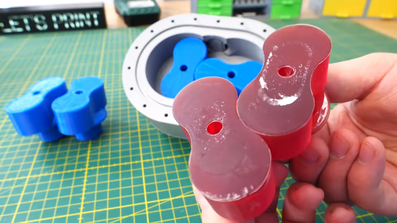
The design uses two figure-eight shaped counter-rotating rotors, or lobes. As the rotors turn, they trap fluid between the rotor and the housing, forcing it towards the outlet. It’s a positive-displacement design, meaning it traps a fixed volume of fluid in each rotation, moving it from inlet to outlet.
The design requires proper timing of the two rotating lobes in order to ensure they maintain the closed volume and don’t impact each other. This is achieved with a pair of timing gears on the back of the pump. The housing, lobes, and gears are all 3D-printed, making this a build that anyone can replicate at home with their own printer.
ABS was used for the rotors for its better handling of friction without melting as easily. However, resin-printed lobes were also employed for their higher tolerances, too, with both designs working acceptably in practice.
The pump still needs more improvement; the hope is to reduce the leaks out of the rear of the pump. [Let’s Print] also intends to add a motor to the pump itself rather than using a power drill to run the device. It’s great to see these 3D-printed pump builds continuing in earnest. Video after the break.


His next one https://www.youtube.com/watch?v=gB_B5vPLLo8 works even better.
When I saw the red resin lobes I couldn’t help but think of integza ;/
Tomatos are disgusting 😉
Roots meters are also used in industry for fluid measurement. The pump shaft rotates in proportion to how much fluid passes through it.
You think you could replace a motor for a stepper and measure out how much water was pumped?
With tight tolerances a filter on the inlet may be a good idea. Perhaps print one? One question: Why not a gear pump? You need a set of gears anyway. Do lobs move fluids that much better than gears?
doesn’t the lobe have a much higher volume displaced per rotations?
It would be very interesting (particularly since I don’t have to actually build it) to see if you could design the drive gears themselves as one stage and the lobes as another in a multi-stage pump.
“resin-printed lobes were also employed for their higher tolerances, too”
I think you mean lower tolerances? As in less tolerant of error?
Lobe pumps such as this are or should be known for the pressure pulses they generate, not a steady flow of air or fluid. For this reason the original style GM pumps were changed from a 2 lobe to a 3 lobe design. Also the rotors were twisted slightly to smooth out those waves but this created another issue, the lobes would extend in length enough to cause problems with end clearance at higher speeds and pressures. Now in the original use that pressure was intended to remain rather low, less than a few PSI because that was all that was needed to scavenge the exhaust in the engines and recharge the intake. Lobe or roots rotor pumps can generate a massive amount of vacuum and or pressure however which is a big reason the design is used for so many industrial applications. The invention was modified to a more increased twist of the rotors to come up with the screw style pump that was massively more efficient and less issues with pulses and rotor distortion, also it would pump a lot more volume because it didn’t have pulse disruption which was not conducive to flow volume.
A pump of this design would lock if the outlet is blocked and either suffer gear damage or burn oit the motor. How can that be prevented?