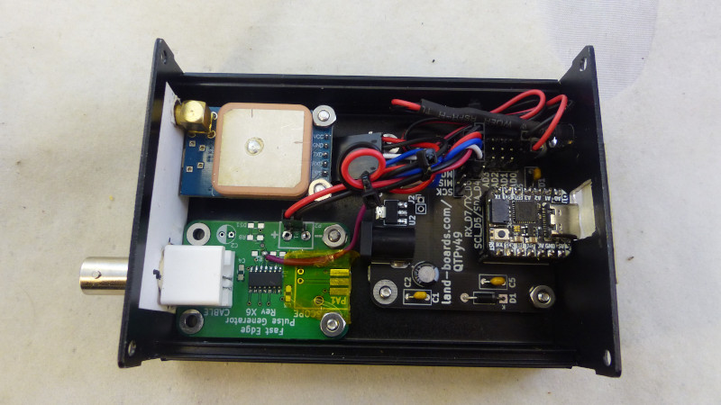
A metrology geek will go to extreme lengths to ensure that their measurements are the best, their instruments the most accurate, and their calibration spot-on. There was a time when for time-and-frequency geeks this would have been a difficult job, but with the advent of GPS satellites overhead carrying super-accurate atomic clocks it’s surprisingly easy to be right on-frequency. [Land-boards] have a GPS 10 MHz clock that’s based around a set of modules.
Since many GPS modules have a 10 MHz output one might expect that this one to simply hook a socket to the module and have done, but instead it uses another of their projects, a fast edge pulse generator with the GPS output as its oscillator, as a buffer and signal conditioner. Add to that an QT Py microcontroller board to set up the GPS, and there you have a standalone 10 MHz source to rival any standard. Full details can be found on the project’s wiki, and the firmware can be found on GitHub.
Careful with your exploration of standard frequencies, for that can lead down a rabbit hole.


“Most accurate” is relative. There were always hobbyists interested in it. They did what they could at the time. So some temperature compensated their crystal oscillators, or put them in ovens. They used cuts of crystals that were inherently more stable. Fifty years ago they’d build WWVB receivers, for the frequency standard, not time. Much better than zero beating to WWV.
When frequency counters became “cheap” and available starting in 1971, it likely became a bigger thing. Accurate readout, but only as good as your reference frequency.
A lot of this was niche, people pushing the limits of the time, putti g a lot of effort into small increments of improvement. But a hobby in itself.
Why bother putting the relatively huge patch antenna uselessly inside a shielded enclosure? I’m guessing the SMA is the real RF input, so why bother with taking up space with the useless antenna?
Or is the deal that a [module with antenna and option for external antenna] is cheaper/more available/better than a [module with just RF in]? (Like, say, the tiny, cheap and capable EBYTE E108-GN01)
Maybe that’s what they had laying around.
It was probably in his parts drawer.
It looks like they used all off-the-shelf components without designing a PCB.
Designing a carrier board for an RF module is kind of a pain. Conceptually it’s not complicated, but RF signals aren’t as forgiving as digital signals, and whatever you build isn’t going to be FCC certified.
Can’t believe they consider 500Mhz (2ns) a “fast” pulse these days. Most of the time you need fast rise time for syncing microwave RF lab equipment in the GHz range. Try 30ps on for size http://www.leobodnar.com/shop/index.php?main_page=index&cPath=124.
But what size is that, I’m more like 3.6 ns around the chest these days, 30ps seems a bit tight even for a kids pinkie ring, unless it’s the diameter.
“and there you have a standalone 10 MHz source to rival any standard.”
The ‘proper’ way of doing this is to have a good oscillator, like an ovenised crystal and phase lock that to GPS. Short term qualities, like jitter and short term wandering depend on the crystal, and long term drift is governed by the GPS. Phase noise can also be very low with this method.
I bought some NEO 6s or 7s myself with the hope of doing something like that only to read later that these modules simply have their CPU bitbang the 10MHz output. I can’t find the original claims but a thread that seems to confirm this is here,
https://www.eevblog.com/forum/metrology/neo-7m-output-frequency-issue/
I’m not sure a clock with a period of 100ns that jumps over a 40ns range can really be said to rival any standard.
It does suggest that an easy way to improve the errors of this circuit by a factor of 10 is to have it generate 2MHz or 12MHz or any frequency divided from 48MHz instead. That said, 2ns jitter is still not good. 2ps for a mems oscillator or 100fs for a crystal oscillator are a lot better.
AMA’s comments are valid. In many ways my HP10811 OCXO is better than a GPS reference.
Any metrologist would mutter “Allan deviation” :)
Then it is not HaD anymore if you buy professional components. This is an 8 USD solution.