[extrowerk] tells us about a new hacker-friendly device – a $20 LTE modem stick with a quadcore CPU and WiFi, capable of running fully-featured Linux distributions. This discovery hinges on a mountain of work by a Chinese hacker [HandsomeYingYan], who’s figured out this stick runs Android, hacked its bootloader, tweaked a Linux kernel for it and created a Debian distribution for the stick – calling this the OpenStick project. [extrowerk]’s writeup translates the [HandsomeYingYan]’s tutorial for us and makes a few more useful notes. With this writeup in hand, we have unlocked a whole new SBC to use in our projects – at a surprisingly low price!
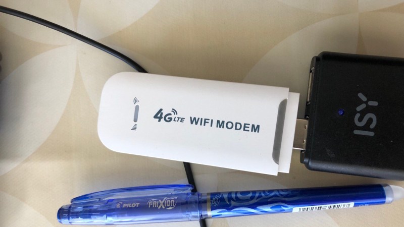
At times when even the simplest Pi Zero is unobtainium (yet again!), this is a wonderful find. For a bit over the price of a Zero 2W, you get a computer with a similar CPU (4-core 1GHz A53-based Qualcomm MSM8916), same amount of RAM, 4GB storage, WiFi – and an LTE modem. You can stick this one into a powerbank or a wallwart and run it at a remote location, make it into a home automation hub, or perhaps, process some CPU-intensive tasks in a small footprint. You can even get them with a microSD slot for extra storage – or perhaps, even extra GPIOs? You’re not getting a soldering-friendly GPIO header, but it has a few LEDs and, apparently, a UART header, so it’s not all bad. As [extrowerk] points out, this is basically a mobile phone in a stick form factor, but without the display and the battery.
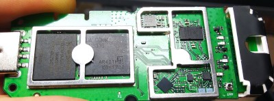 Now, there’s caveats. [extrowerk] points out that you should buy the modem with the appropriate LTE bands for your country – and that’s not the only thing to watch out for. A friend of ours recently obtained a visually identical modem; when we got news of this hack, she disassembled it for us – finding out that it was equipped with a far more limited CPU, the MDM9600. That is an LTE modem chip, and its functions are limited to performing USB 4G stick duty with some basic WiFi features. Judging by a popular mobile device reverse-engineering forum’s investigations (Russian, translated), looks like the earlier versions of this modem came with the way more limited MDM9600 SoC, not able to run Linux like the stick we’re interested in does. If you like this modem and understandably want to procure a few, see if you can make sure you’ll get MSM8916 and not the MDM9600.
Days of using WiFi routers to power our robots are long gone since the advent of Raspberry Pi, but we still remember them fondly, and we’re glad to see a router stick with the Pi Zero 2W oomph. We’ve been hacking at such sticks for over half a decade now, most of them OpenWRT-based, some as small as an SD card reader. Now, when SBCs are hard to procure, this could be a perfect fit for one of your next projects.
Update: in the comments below, people have found a few links where you should be able to get one of these modems with the right CPU. Also, [Joe] has started investigating the onboard components!


He can run gcc on that stick. I am totally not expecting that.
You can run nearly ANY linux arm64 application on the stick, even KVM virtual machine. The only limit is the little 512MB RAM.
Does anyone have an aliexpress link to the correct item? I see a ton of items on sale but they don’t indicate whether they use MSM8916 or MDM9600.
some of the listings on fleabay do indictate ‘qualcomm 9600’ or ‘qualcomm 8916’, so I recommend doing a search with descriptions included to find those listings.
This worked for me, but no guarantee.
Alsi this version doesn’t had an SD card slot, sadly.
https://www.aliexpress.com/item/1005004150595233.html
Układ: Qualcomm 9600
sorry this is not 8916 ;(
Please do a ctrl+F with my username.
The listings are.. kinda confusing.
I’ve picked up a pair from a different seller. They’re listed.. confusingly, and I’m guessing they ship whatever’s on hand. Both the ones I got from https://www.aliexpress.com/item/1005004198680336.html are 8916s (according to the splash page on the router ui) with one sim, GPS detected as 0 lat and long, and the ability to switch to a second, non obvious sim card. Haven’t tried reflashing them cause I actually need them to be 4G APs for a bit
https://aliexpress.com/item/1005004149094857.html?gatewayAdapt=glo2rus&sku_id=12000028198017831&spm=a2g0s.12269583.0.0.5b1b7c8b7Z22I3 this one 8916, but i install openstick, but don’t clue as setup LTE connection. Has only
wwan0qmi0: disconnected
“wwan0qmi0”
cdma (qcom-q6v5-mss, bam-dmux), hw
I’m still a little new to hardware hacking so I have to ask, with having a full Linux distro on this, could it reverse SSH tunnel to my home setup so I can link to it from the house regardless of the sim card it’s using?
as long as your home setup has a public IP! Otherwise, you can use Tailscale – works wonders for me for the same purposes.
Thanks for the reply.
My home broadband has a dynamic ip, but SSH into my router and VNC of my pi Zero work fine using NoIP DDNS service.
A reverse tunnel would work just the same as with a fixed IP?
As long as your DDNS works well and you use the DDNS domain name instead of the IP when creating the tunnel, it oughta work! One thing though – I’d look into something like a Wireguard connection instead of SSH for a tunnel, not only it’s more featureful, it’s also more reliable wrt autoconnects and unreliable links, in my experience.
Not heard of tailscale, I’ll check it out, thanks
Thank you very much for the article and your url.
I ordered two sticks from your url 2 weeks ago and received the devices already today.
I can confirm your instructions worked without any problems and both devices have debian installed now :)
I’m a bit concerned about the mirror “http://mirrors.163.com/debian/” used in /etc/apt/sources.list, and http://repo.mobian-project.org/ used in /etc/apt/sources.list.d/mobian.list, because both don’t look official. I guess they contain patches for the hardware somewhere, but imho it would feel much better if both repos would only contain the patched packages and not override all official ones.
Hi from 2024!
https://mobian-project.org/ seems to be an alternate domain for https://mobian.org/ : links go to the same places and it looks the same.
I pinged them and they’re the same IP.
https://en.wikipedia.org/wiki/Mobian?useskin=monobook Mobian is a real project.
The 163 mirror may be unofficial, per the official list at https://www.debian.org/mirror/list-full#CN .
It is striking that everyone involved has seen fit to detail every aspect of the project *except* the most essential bit: a reliable way to get hold of the stick in question… it’s probably safest to regard this as non-repeatable until there’s a source for it, just like all of those nifty-looking software projects whose only documentation is a Youtube video.
Because nobody want to be responsible when you get a cost-reduced, crippled, incompatible version in the exact same enclosure.
that’s specifically why I added the caveat, so that people know what to look out for and can find a source. not everything comes on a silver platter!
https://m.aliexpress.com/item/3256804090010937.html?spm=a2g0n.order_detail.0.0.14c5f19cJMa9Hr
The black stick says MSM8916 on this listing
That listing has some feedback that it doesn’t work in some countries, but also one, that it has the 8916 chip instead of the advertised 9600….
Isn’t that perfect? We’re looking for the MSM8916. Who here even cares about the sim? It seems to me that we’re in this to make an affordable sbc, not a phone or modem.
My sticks just arrived! I can confirm that the black sticks really are MSM8916 as advertised. It took them 2 weeks to arrive to me here in Arizona from China. Now to get hacking…
Oh man, this is checking boxes for me!
Why does an LTE modem have an Android distribution on it? What’s it doing? Why is the processor this powerful?
Is this just a bigger processor swapped in because the smaller ones became unobtainable? Or is this thing MITMing all your LTE comms?
Likely a case of ‘Hey we’re already making a ton of these for phone SKU’s. Why not run up a few lines of the same thing, except without keypad, dispplay, or battery?
Great Idea! Also, I often get decent discount at shops for parts that were not selling well.
Stingray on a fob, for 3rd world intelligence services on a budget.
Someone with deep cell network knowledge should implement a stingray on this thing. If the NSA can snoop us, we should be able to snoop them. Fair’s fair. Goose, gander etc.
Might need a linear to work, but good news, Alibaba has cheap linears.
TL;DR: using Android is easier and cheaper than spinning up their own distro because it already handles 95% of the stuff they’d need to implement if they did it from scratch
Android was just the cheapest and easiest option to go with when deciding on what to run on the thing. Think about it, android already has all the drivers and utilities for setting up an LTE connection and handling network routing (hotspot). All the manufacturer has to do is rip out all the gui bits, throw in a couple of auto configuration scripts for stuff like a wifi AP, a web interface for additional configuration (APNs, sms, etc.) and boom you have an LTE hotspot. As for why it’s so powerful, the main chip is a SOC meant to power whole android phones and tablets it’s not just a modem. I wouldn’t be surprised the chips in these are inexpensive QC rejects from Qualcomm
Exactly this. I’ve seen medical devices that had to call home, and they came with a locked-down Motorola smart phone that had the android UI disabled. Literally powers on with Motorola & the carrier logos, then shows the most simple text UI reminiscent of fastboot / recovery mode that shows signal strength and IMEI. No user-interactive controls beyond power off.
Are you referring to a CPAP?
Nope, Zoll provides them with their LifeVest wearable defibrillators.
They come with their bootloaders pre-unlocked (thanks, Zoll). They picked whatever the cheapest phone was they could they could hack up, flashed their own bootsplashes, and set it up so it’d boot into Android and directly into their APK to handle everything.
Best part: the APK is “com.lifevest.zuul”.
“das ist ein Game-Boy Advance…”
It probably also helps that Android moves forward and SoCs get obsolete for phones very quickly. Easier to sell a 4G stick running Android 8 than a phone with the same.
No, just a convenient way to use cheap, somewhat older SoC that if build in a todays smartphone would not sell.
I feel silly but I can’t find what the guy bought in specific. Rather just the class of device bought.
That said, I am reminded of a hocky puck sized Wifi/LTE modem my aunt had about a decade back, andrealized if I could run a ‘normal’ linux on it and if there is on device storage it’d make a decent little hobby box.
Can the USB port on this be configured to not only power the device, but to be a host to another USB device? If so, adding a small USB hub would allow you to use multiple devices with this.
By default, the usb port would be a gadget or device port, rather than a host.
That said, since many phones support OTG, that may also be the case here, and it might be possible to have the dongle be a host with an appropriate adapter and internal programming.
Note that an OTG cable has the ID pin to allow the device to recognise that it should enter OTG mode and assume the host role, while these devices only have a USB A connector which omits the ID pin. Hence the requirement to programmatically enter host mode. Also, you would need the hub to source power to the dongle as well as any other devices connected to it.
Wonder if you could use UART to tell it to enter host mode?
It definetly can do that, here somebody does exactly that:
https://blog.csdn.net/github_38345754/article/details/121481021
I just bought a [female USB to female micro-USB adapter](https://www.aliexpress.com/item/1005003139375815.html?spm=a2g0o.order_list.0.0.74441802T46tA4) to convert the male USB of the stick to female microUSB. From this point it is like a phone.
Then i bought a [microUSB hub](https://www.aliexpress.com/item/1005002547500579.html?spm=a2g0o.order_list.0.0.74441802T46tA4) which provides 2 USB-A port and elt me power the whole stuff through a microUSB port.
I am waiting those to arrive, will report back.
Searched my available sources and only can find it with the Qualcom 9600 and 9200 anyone has good source that is not a Chinese supplier? Thanks
Not sure how $20 is a good deal, 6 years ago I bought 3 Moto Es for $20 each, those have the same chipset, twice as much RAM, and include a battery and screen. They even held up to a few years of cryptocurrency mining, something that would burn out cheap ZTEs after a few months to a year. Once mining wasn’t profitable anymore, I now have those Moto Es waiting for use in some other project.
$18 is for shipping, actually you can get some for $2 each in China, impressive!
You can build a crypto miner cluster with it.
I just bought a moto g4 play XT1601 (as is- couldn’t read sim cards) as well as several of these 4G LTE MSM8916 sticks to see if I can get openstick running on both instances of MSM8916 (the moto g4 play has MSM 8916 and 2GB DDR3 RAM). The 4G LTE sticks on Alibaba were $12 with free shipping and the as-is g4 play was $13 with free shipping. Same cost, but more ram and a working screen. I’m just curious what I can do with it.
Pis are highly sought after because they have a vast developer network, receive regular updates, and are designed for DIY. Taking any ARM SBC with similar chips and trying to replicate a Pi just turns it into a Linux box that can’t install kernel updates.
It’s just not the same thing, and the pricing of Pis reflects that more than just supply chain issues. We know there are plenty of cheap chips out there, but there’s only one brand of ARM SBCs that gives you the flexibility and support as if you were building a home PC. There is just no competitor for that ecosystem yet.
It seems that this chipset has some additional functionality built in: Adreno 306 graphics, Bluetooth, GNSS (GPS, GLONASS, BeiDou).
On this dongle, the GNSS probably doesn’t have an antenna, but I wonder if Bluetooth shares the WiFi antenna?
Not being a Linux guru, let me ask a possibly dumb question. Could you use the Adreno as if there were a display connected, but instead, view the output on VNC? I know you can do this on a computer with a physical display connected. That way, you wouldn’t be limited to only running text programs.
BTW, I ordered two similar looking dongles from Amazon for $23 each (two days, instead of two weeks). They showed as having a uSD slot, so hopefully they have the correct chipset. Wrong LTE bands for the US, but I don’t care.
X11vnc lets you connect to a virtual display, no display needed :)
I have seen a Chinese guy doing exactly this, i think the factory android image runs even the gui, it just doesn’t have any display attached. So running doom on it should be possible.
Can you post a translation? I tried Google Translate, but for some reason, it starts to show me the blog page, and then redirects me to some main page.
For some reason, my reply didn’t post beneath what I was replying to. I was asking about a translation of this page, which shows how to setup USB host mode: https://blog.csdn.net/github_38345754/article/details/121481021
Now I need a 4G basestation to connect to it. Anything opensource to transform an hackrf card into a 4G basestation?
please make BATMAN mesh linux network
it is small and cheap and meybe help in war time or emergency
It’s not $20 but only ¥20 about $1-2 on AliExpress in China.
you are laing
in aliexpress is about 20$
I think it’s ironic that one of you is called Lucifer, the father of lies, and the other is called tryhrth which looks like truth.
Anyway, I’ve seen it for as low as $12 on aliexpress. ctrl + f my name for a link to what I found
I’m waiting on one to arrive from Aliexpress for 12 GBP which at the moment is about 14.55 USD.
Said the correct chip number, let’s see what I get
“in China”, not from China – ofc locals get different listings and prices, the “free shipping” is covered by the item price being higher.
I did something like that once.
I have a Huawei LTE router, on digging I found out that it runs Android.
Adb is accessible via network and running “adb shell” returns a root terminal.
I have Disable unnecessary services (VoIP + SIP, VPN etc) to save memory.
Then I have mounted an Adguard Server and with a HDD through the USB port a torrent download server (Transmission WebRPC).
Those modifications had no impact on performance and were more than enough.
The characteristics were CPU Hisilicon x2 1Gz, 512MB RAM, 1Gb Flash (only 128Mb accessible, the rest of the partitions are system and read only).
interesting I have this exact modem
I think I found the same modem with msm8916 chipset here: https://m.alibaba.com/product/1600463210784/TIANJIE-Qualcomm-MSM8916-unlocked-mini-4G.html
non-mobile link: https://www.alibaba.com/product-detail/TIANJIE-Qualcomm-MSM8916-unlocked-mini-4G_1600463210784.html
My Amazon order arrived today. I have Debian installed on one of the two devices that I ordered. I did have a problem with fastboot on Win10, but found the answer here: https://beebom.com/fastboot-not-detecting-device-windows-10/
I am currently having a problem with installing nano. I am getting name resolution errors. I’ll have to brush up on my Linux. I haven’t done anything with it in several years, and all of the configuration stuff I used to know has changed.
Here is a link to what I bought. Note that despite the description and picture, it has no TF slot. There are several vendors selling the same thing, at least one for $2 less. Look for the picture of the guy with glasses, holding it next to his head.
https://www.amazon.com/dp/B07NY4X5YP/
Looking at the circuit board, I see pads for a UART, an antenna (which one?) and other stuff. For later investigation…
I just put together a web page that may have some helpful information about this: https://www.zianet.com/jgray/openstick/
That is a well written web page you have there. As for the location chosen for the device, it seems I was also thinking of the same location.
nicely done, thank you for writing your experience up and sharing it with us! some notes:
That is not a TF socket footprint, it’s a footprint for a small DFN-8 chip – in fact, there’s two of these, as you’ve noticed. I wonder what’s that for – I’ll have to wait until I can get one of your modems. However, if it’s a flash chip and happens to use SPI, we could absolutely mod a microSD card slot on there, just that it’d be lower-speed, perhaps.
Certainly not – in fact, SIM interfaces are more UART-like.
..hope so, but what makes you think that?
the Bluetooth support circuitry might not even be wired up to the chip, I’m afraid =( that said, there’s hope, of course!
The UART and SPI things absolutely could use a test! My guess is that SPI would be quite usable from Linux, and UART always tends to be – unless it’s some comms channel between two chips on the board or something.
I was going by the picture that showed a TF socket, and assumed that was what the footprint was for. It looks like you know more about that than I do. Also about SIMs.
As for the buttons, I found some documentation for a development board that uses the Snapdragon 410. It talks about reassigning buttons. That is just some of the additional documentation that I need to read through. I’ll update the web page later.
I haven’t tried Bluetooth yet. I assume it uses the same antenna as Wifi, though.
The UART is next on my list of hardware to investigate. I2C and SPI will be later.
For further discussion, it might be best for you to email me (take the username and domain in the URL of the web page). Any information about these dongles will be added to my web page as we learn new things.
I noticed in your OpenStick investigations that you had two pads labeled Vi & Gnd and crossed them out. I believe these are antenna pads.
In your photos you have the plastic tip with black tape still installed on your board but in Mizsei Zoltán’s photos he’s removed the plastic tip. If you notice in Mizsei Zoltán’s photos where the plastic tip would be, you can see two pads similar to the one you marked up however one is populated with a connector. That connector interfaces to the black tape on the plastic tip which is actually a metallic tape antenna.
Curiously, if you inspect the plastic tip you’ll see there’s actually two contact pads and one lines up with the unpopulated pad on the board. So it appears there are actually 4 antenna pads on the board but only one is populated.
Anyone else having problems downloading the debian image?
It’s hosted on GitHub, so there shouldn’t be a problem with that. Unless GitHub is doing some outage weirdness (can check online), it’s most likely your internet connection.
To save others from making the same mistake I did, you need to configure the WiFi on the dongle as a client, with no SSID. Then use “Activate” to connect to your home WiFi router. Select your SSID, then you will be prompted for a password. Finally, your dongle will be connected to the internet.
But now, when I try to do an apt-get update, I’m getting various errors. I can ping google.com and others, so I know that the internet is finally working.
See my web page for an update on this. I’ll be adding information as I figure things out.
I think I have the same one. I opened it and it has a chip marked as “PM8916”. When I log in to the router page, there is a “upgrade” option which accepts an “apk” file and in windows the device name is “Android”. But I cannot connect via ADB. The router IP is “192.168.100.1” and if I try to connect by running “adb connect 192.168.100.1” it says connection refused. Anyone has any idea?
That PM8916 chip is the Power Management IC (PMIC). That is the same one I have. However, the default IP you have is different. I have 182.168.68.1, which is the same as documented by Extrowerk. So, without unsoldering the metal shield to look for the MSM8916, I don’t know how to confirm that you have the correct LTE dongle.
I followed Extrowerk’s instructions, and managed to flash Linux. If that isn’t working for you, perhaps you don’t have the correct dongle.
Typo – that IP should be 192.168.68.1
My mistake. The .100.1 IP is how the dongle comes. The .68.1 IP is what it gets after flashing Linux.
I tried to change the change the ip address to “192.168.68.1” just to test if it works. The modem stopped working at all. So I opened it, long pressed the power button and everything was reset. So it works now.
Although my device doesn’t normally show up on “adb devices” list, when I do a factory reset, it briefly shows up in “recovery” mode. So I am guessing a valid android device is in there, but the system has developer mode turned off so it doesn’t normally shows up in “adb devices” list.
> adb connect 192.168.100.1”
I have *nowhere* documented a step like this.
Stop reinventing the wheel and causing headache for yourself while doing so, just follow the simple step-by-step guide i have published.
I tried to connect via network because normally “adb devices” doesn’t show my modem on the list. It might not be the exact device you guys have. Or the software version is different which doesn’t have ADB connections enabled. Since the modem upgrade page accepts an apk file, I will try to upload a modified apk file and open a reverse shell. I will update here if I succeed.
Listen to Extrowerk. You’re doing things the wrong way.
I found a few potentially helpful links:
https://wiki.postmarketos.org/index.php?title=MSM8916_Mainlining&mobileaction=toggle_view_mobile
https://developer.qualcomm.com/download/sd410/snapdragon-410e-technical-reference-manual.pdf
https://developer.qualcomm.com/download/sd410/snapdragon-410-processor-device-specification.pdf
https://trustedfirmware-a.readthedocs.io/en/latest/plat/qti-msm8916.html
https://github.com/msm8916-mainline/qhypstub/blob/main/README.md
https://device.report/qualcomm%20technologies/msm8916
——————- The Following Are Helpful Links Posted By Others On This Thread:
https://www.zianet.com/jgray/openstick/
https://www.zianet.com/jgray/openstick/08Aug2022.html
https://blog.csdn.net/github_38345754/article/details/121481021
https://github.com/HandsomeYingyan
https://github.com/OpenStick/linux
https://github.com/OpenStick/OpenStick/releases
https://github.com/OpenStick/lk2nd
https://extrowerk.com/2022/07/31/OpenStick/
https://developer-archives.toradex.com/knowledge-base/how-to-install-microsoft-rndis-driver-for-windows-7
https://beebom.com/fastboot-not-detecting-device-windows-10/
https://www.kancloud.cn/handsomehacker/openstick/2636505
Hi,
is there a short comprehensive list (aka howto), what’s needed to change the bootloader and flash debian on the device?
The chinese sites should be worth translating, but google translate does not help too much there.
Thanks a lot!
Cheers
4920441
I’m not sure what you have in mind, but Debian is what is already running on the thing. The Chinese blog site documents what the guy did to figure out how to flash a bootloader and Debian. I used Google Translate, and it did a decent job on most of the page. A few small sections of text were left in Chinese, but i copied/pasted them to get them translated.
Maybe try to click the *first* link in the article.
*Facepalm*…. how did I miss that? aaargl:-)
Once loaded with Linux, could it run an octoprint instance?
The Zero 2W is meant to handle it well so, I can’t help but think if this would be an even cheaper option?
https://notenoughtech.com/raspberry-pi/running-octoprint-on-raspberry-pi-zero-2-w/
Has anyone had luck actually using the LTE modem after flashing this? I had a stick that detected the SIM just fine before flashing. After flashing it shows the sim as not being inserted:
root@openstick:/# mmcli -m 0
———————————–
General | path: /org/freedesktop/ModemManager1/Modem/0
| device id: 1ec3156c870d523e616cee0ef4dcf0676f78xxxx
———————————–
Hardware | manufacturer: 1
| model: 0
| firmware revision: MPSS.DPM.2.0.2.c1-00178-M8936FAAAANUZM-1D 1 [Nov 04 2016 02:00:00]
| carrier config: ROW_Generic_3GPP
| carrier config revision: 02010801
| h/w revision: 10000
| supported: gsm-umts, lte
| cdma-evdo, lte
| lte
| cdma-evdo, gsm-umts, lte
| current: gsm-umts, lte
| equipment id: 86176603523xxxx
———————————–
System | device: qcom-soc
| drivers: qcom-q6v5-mss, bam-dmux
| plugin: qcom-soc
| primary port: wwan0qmi0
| ports: wwan0 (net), wwan0at0 (at), wwan0qmi0 (qmi), wwan1 (net),
| wwan2 (net), wwan3 (net), wwan4 (net), wwan5 (net), wwan6 (net),
| wwan7 (net)
———————————–
Status | state: failed
| failed reason: sim-missing
| power state: off
| signal quality: 0% (cached)
———————————–
Modes | supported: allowed: 2g; preferred: none
| allowed: 3g; preferred: none
| allowed: 2g, 3g; preferred: 3g
| allowed: 2g, 3g; preferred: 2g
| allowed: 2g, 4g; preferred: 4g
| allowed: 2g, 4g; preferred: 2g
| allowed: 3g, 4g; preferred: 4g
| allowed: 3g, 4g; preferred: 3g
| allowed: 2g, 3g, 4g; preferred: 4g
| allowed: 2g, 3g, 4g; preferred: 3g
| allowed: 2g, 3g, 4g; preferred: 2g
| current: allowed: any; preferred: none
———————————–
Bands | supported: egsm, dcs, pcs, g850, utran-1, utran-5, utran-8, eutran-1,
| eutran-3, eutran-5, eutran-8, cdma-bc0
———————————–
IP | supported: ipv4, ipv6, ipv4v6
root@openstick:/#
anyone have a tip as to what might be wrong?
It’s possibly down to a switch contact that is no longer mapped or has been remapped after flashing.
I’ve setup a stupid number of RUT955 routers, the newer versions have a little metal plate on the side of the SIM tray that bridges a set of contacts, even with a sim inserted RUT955 refuses to accept there is a SIM present if this contact is not made.
Could be something deeper but this is all I can think of at the moment.
Using the at+cpin? command with minicom on the /dev/wwan0at0 interface gives a similar SIM missing error, so my guess is that the physical SIM switch contact GPIO status somehow isn’t making its way through to the modem. There is an open bug about this on the OpenStick Github page.
https://github.com/OpenStick/OpenStick/issues/12
Thanks for the info, I’m still a finding new commands each day to get the info I want.
I’m about to order a 2nd one of these, I’ve been holding off on flashing till the modem issue has been dealt with, once my 2nd is on the way I’ll flash the first one.
Can you please share your modem drivers? Flashed mine but forgot to save them upfront.
https://github.com/OpenStick/OpenStick/issues/33
I’ve not progressed further than using one as it is out of the box so far.
Not currently sure where I’ve put them but if I find them I’ll try pull the drivers for you, could be quite a while though.
Same for me
Just had another read of the OP Chinese post on this device, it says….
“Supports 4G wireless network cards whose silkscreens start with UFI001B, UFI001C, SP970, and UZ801.”
a little lower dowm there is a table giving the GPOI for the LEDs for each of the above pcb silkscreen.
Mine silkscreen is UF896_V1.1 so for the time being at least I’ll not have the LTE when I flash mine.
Nop, been there.
Modem will stuck in connecting mode
> wwan0qmi0 gsm connecting (prepare) modem
with this error:
Jul 13 17:42:49 openstick ModemManager[330]: [modem0] couldn’t enable interface: ‘Couldn’t set operating mode: QMI protocol error (52): ‘DeviceNotReady”
I also tried other images from OpenStick and finally bricked dongle with boot-uz801.img
I have the same device UF886 and I want to send/recieve sms.
So first I have now backed up my flash and dumped dmesg, config.gz and extracted several dtb..
I would like to know where I can see in the plain android the gpio mapping or see a file where/which gpio is toggled if the sim is inserted as obviously this is why openstick will not work with sms.
If I could send/recieve sms programmatically I would be fine with the stock android, too – as it’s so rooted. I can add and remove what I want now already. Thou a clean make flash all would be nice.
Hello, can you provide your dump please?
I was seeing the same “sim-missing” failed status in ModemManager after flashing Debian.
To get it working again, I took the white plastic casing off, removed the thin metal covering the SIM slot (had to gently pry it off a little after cutting the solder on both sides with a razor blade) and then (I know) taping the SIM card down making sure the 6 pins were in contact with the slot.
Worked like a charm after that. My guess is that the pins on the SIM slot just weren’t making full contact with the SIM card before.
Hi Richard, what is the silkscreen of your PCB?
I think mine is one of the types that have been found to have LTE issue after flashing, as stock both of mine have worked fine.
I have the same issue. Modems with firmware name beginning with MPSS are reported to not working properly with LTE on debian. I ordered two sticks, one with MPSS and the other one with UZ801 and the last one is working flawlessly.
I don’t think that the SIM is enabled after flashing Linux. In the device tree, both UARTs are defined,but one is disabled. The enabled UART is assigned as a console during boot (solder wires onto RX, TX and GND).
Either UART can be assigned to function as a SIM interface (UIM as Qualcom calls it). In device tree, sim_sel and sim_en are defined, but disabled.
I’m trying to get the disabled UART enabled, to use as a second serial port. See what I have found on my web page.
The sim_sel and sim_en are GPIO signals. This may prove useful to you:
https://embeddedbits.org/new-linux-kernel-gpio-user-space-interface/
I may be a bit dim, but I can’t get either of the 2 devices I bought (which according to their web interfaces are the correct chipset) to show up with adb. I’m assuming they aren’t set up for usb debugging and I can’t see anything on either (totally different) web interface to set it up. nmap doens’t show any services on the usb0: interface it stands up either.
The devices shows up as 65MB storage device (both) and expose something of a filesystem.
Is there a file somewhere I need to edit to set up debugging?
Nothing anywhere obvious (to me at least) like /boot, although I don’t see a kernel anywhere so I’m assuming I only have *some* of the filesystem.
Cheers
I followed Extrowerk’s instructions and was able to flash both of mine. If that doesn’t work for you, then perhaps you don’t have the correct ones.
The other thing you can try is to press the “reset” switch just after plugging it in. That is supposed to put the device into flashboot mode. I didn’t need to do this, but was told that this works.
Thanks for the reply Joe. Extrowerks instructions rely on debug being enabled, which unfortunately isn’t the case …
Dmesg and lsusb report the correct chipset and an Android device and the chips are labeled as such (and that’s never wrong, right?…..) so I’m *fairly* confident I’ve not been ripped.
Was wondering about the resets. The build quality is a bit crap so they are metal dome type switches rather than an actual hardware switch so it’ll be tricky, but doable. The timing will be critical as the boot process takes a bit of time and appears slightly different for both devices. The layout of both boards is slightly different as well. One has the I/O points on the edge, the other does not.
I guess the next step is digging out the uart tools. Anyone have luck with that?
I had the same issue. I was able to get past that.
– Open the casing, there should be a switch. Plug in your device, wait a few moments till it turns on.
– Run this command in the terminal -> adb wait-for-any-recovery && adb reboot bootloader
– Press and hold switch, the lights will change color/flicker a few times. Let go of the switch and after a few moments your device should go to bootloader mode. From there you can resume the process mentioned in Extrowerks article.
Do you mind if I add your instructions to the web page I made about this?
Awesome Nazmul. Thanks for that. Just have to futz with the damn tape and dome to make the switch work.
Maybe if I’d read *all* the previous comments properly, I’d have seen you went through similar grief…
.. Noob move on my part. But to be fair, I’ve been a lurker for years and this is the first post I’ve ever commented on, so …
I have now looked at several web pages that tell you how to make a device tree overlay. However, the syntax on some is different than others, so I’m not sure which is correct. I’d appreciate it if someone more knowledgeable would look at what I have and tell me what I’m doing wrong.
There is no separate dtb file, so I created a dts using this command “dtc -I fs /sys/firmware/devicetree/base”. The file is too large to post, so here is a Dropbox link:
https://www.dropbox.com/s/ndn9im660ut84t6/DeviceTree.dts?dl=1
This is the overlay that I created:
https://www.dropbox.com/s/c786g67hcsenvgg/serial2.dts?dl=1
As you can see in the full device tree, the serial port that I am dealing with is already defined, but disabled. I just want to enable it. Optionally, setting the alias would be good, as the enabled serial port has one.
When I compile the overlay with “dtc -O dtb -o serial2.dtbo -@ serial2.dts”, I get the following error:
Error: serial2.dts:8.20-21 syntax error
FATAL ERROR: Unable to parse input tree
Sure Joe, no problem. I think it would be helpful for others as well
Got mine on this link and it arrived in the UK yesterday, I popped the casing and it is the correct chip for this project.
I’ll enjoy digging into this but I think I’ll hold back to see what happens with modem use after flashing.
https://a.aliexpress.com/_mL7sE76
Can you open it please and publish silkscreened version from PCB?
This is a great little linux device. Unfortunately I accidently removed network-manager and now I have no access to it anymore via adb or network/usb. has anyone successfully used the reset button to get it into fastboot/recovery? I am having no luck so far.
Did you try ssh’ing into it? Also, there is a serial console running. Solder wires for tx, rx, gnd. Use 115,200, n, 8, 1. Failing all of that, look above for Nazmul’s instructions. See my web page for more info.
While removing network-manager i watched it removing wlan0 and usb0. I was kicked out immediately. no network interfaces are up anymore. Maybe if I would have put entries in /etc/network/interfaces then I might have been able to get back in.
I cant reach the website linked to your username. it times out.
https://isitup.org/www.zianet.com
The same happened with mine. I was unable to fix it afterwards.
I just tried the website. It worked for me.
I bricked mine, but managed to boot into EDL mode (pressing the reset button while plugging it into USB). From there it’s possible to reflash a stock image and afterwards debian again… If you’re interested I can help you with that.
Yes please elaborate. I tried a few procedures where I held the button and connected it and looked for the device with adb and fastboot but I didnt see it anymore.
TIA
If you hold the button and connect it, it starts up in QDL/EDL mode and you can read and write its flash using this tool: https://github.com/bkerler/edl – it’s written in python so I think you can also install it using pip. Here you can find a “stock” firmware in the UFIOO1C_MB_V01_JZ_ROM subdir: https://drive.google.com/drive/folders/1UT6yQoI-s5d02pTQJj9MCErYoF6Juzc9
The command I used was “edl qfil rawprogram0.xml patch0.xml .”
Good luck!
Should the device show up in ‘lsusb’ or ‘Device Manager’ while in this edl mode?
Mine does not. it appears to be dead, no LED’s ever any more. no usb devices enumerating. I pressed the button on the PCB while plugging it in, held it for varying lengths of time before releasing it, no luck so far.
My device is the same as the one in the pictures on the first post of this thread.
https://forum.openwrt.org/t/qualcomm-msm8916-lte-router-384mib-ram-2-4gib-flash-android-openwrt/131712
Hmm when I plug mine in while holding the button, LEDs are not doing anything.
However, lsusb shows this line: “ID 05c6:9008 Qualcomm, Inc. Gobi Wireless Modem (QDL mode)” which is how I found out about QDL mode in the first place…
to answer @jockl I was first in the same situation as you, nothing in the shell as well.
After retrying unplug plug again by maintaining reset button pressed and then unpressed, and relaunching the command indicated “edl qfil rawprogram0.xml patch0.xml .” from inside the Roms directory, I was able to see lot of logs in shell indicating flashing.
However no led blinking, so I suppose Led blinking is only when the Openstick is on its own
I was super excited to see this awesome hack and found a promising one that I purchased from alibaba; the primary chip checks out – MSM8916; pictures for reference https://snipboard.io/EMeKF7.jpg , https://snipboard.io/9ExrwU.jpg
But the challenge is, I’m not able to get an adb connection to it. The device is pingable and UI is accessible on 192.168.100.1, now here’s something new – there is no “upgrade” function in the UI either and after a bit of tinkering, found it is running a Eclipse Jetty webserver, rather than I what I can guess the others are running – an android app.
On connecting to USB, it lists as a RNDIS device, disconnects and reconnects again in a few seconds
=================================================================
[Aug20 15:04] usb 3-8.1.4: new high-speed USB device number 41 using xhci_hcd
[ +0.101530] usb 3-8.1.4: New USB device found, idVendor=05c6, idProduct=f00e, bcdDevice=ff.ff
[ +0.000010] usb 3-8.1.4: New USB device strings: Mfr=1, Product=2, SerialNumber=3
[ +0.000003] usb 3-8.1.4: Product: Android
[ +0.000002] usb 3-8.1.4: Manufacturer: Android
[ +0.000002] usb 3-8.1.4: SerialNumber: 0123456789ABCDEF
[ +0.006808] rndis_host 3-8.1.4:1.0 usb0: register ‘rndis_host’ at usb-0000:00:14.0-8.1.4, RNDIS device, ce:12:d8:cd:30:e0
[ +8.630068] usb 3-8.1.4: USB disconnect, device number 41
[ +0.000192] rndis_host 3-8.1.4:1.0 usb0: unregister ‘rndis_host’ usb-0000:00:14.0-8.1.4, RNDIS device
[ +0.257230] usb 3-8.1.4: new high-speed USB device number 42 using xhci_hcd
[ +0.100923] usb 3-8.1.4: New USB device found, idVendor=05c6, idProduct=f00e, bcdDevice=ff.ff
[ +0.000009] usb 3-8.1.4: New USB device strings: Mfr=1, Product=2, SerialNumber=3
[ +0.000004] usb 3-8.1.4: Product: Android
[ +0.000002] usb 3-8.1.4: Manufacturer: Android
[ +0.000002] usb 3-8.1.4: SerialNumber: 0123456789ABCDEF
[ +0.004680] rndis_host 3-8.1.4:1.0 usb0: register ‘rndis_host’ at usb-0000:00:14.0-8.1.4, RNDIS device, 3e:d1:02:cf:1d:75
=================================================================
I’m a noob and perhaps I’m missing something very obvious – any insights?
Did you get anywhere with this modem? I’m stuck at the same point.
I found a hint from here: https://www.mydigit.cn/thread-373932-1-1.html
I found the page by searching for the model number on the PCB: fy_uz801_v3.2
FIrst, visit http://192.168.100.1/usbdebug.html which should allow ADB connections
You have a yet another new revision of UZ801.
So they not only keep updating the software but the boards themselves as well.
Been running mine stock for a couple of days, works fine as its built, I’ve done a port scan using “pingtools” from my phone and the following 3 ports show with stock firmware.
53
80
8080
Tried to SSH into 53 using ‘admin’ and ‘root’ as user name but it just hangs.
I’m hoping there is a way to poke at it while stock to figure out what’s different between stock and Linux for the modem “no sim” issue.
Perhaps this is an interesting variant? It has a battery:
https://www.alibaba.com/product-detail/150Mbps-MSM8916-Portable-4G-SIM-Card_1600341187082.html
I got mine from https://amzn.eu/d/6UEapVO and https://amzn.eu/d/6QXY1tJ they both are labeled with UFI_003_MB_V02 and I also have issues with 4G, but at least SIM and GSM seem to work on stock android. That’s why I rooted the device for further debugging… The app “Qct Modem Capabilities” shows lte bands B1, B3, B5 and B8 are supported. In case anyone is interested in an easy way to root stock android:
download:
https://eu.dl.twrp.me/seed/twrp-3.1.1-0-seed.img
and
https://downloadmirror.co/1MbB/SR5-SuperSU-v2.82-SR5-20171001224502.zip
then
adb push SR5-SuperSU-v2.82-SR5-20171001224502.zip /sdcard
adb reboot bootloader
fastboot boot twrp-3.1.1-0-seed.img
#wait some time until adb is up
adb shell
twrp install /sdcard/SR5-SuperSU-v2.82-SR5-20171001224502.zip
reboot
you can access the gui with some adb screenshot tool like
https://marian.schedenig.name/wp-content/uploads/adbcontrol.zip
Hi, so after rooting, the GUI or “phones menu” screen is available on the PC?
Does this mean that if we only need to run a Android APK it can be installed this way?
Hi!
Root is not needed for that – just adb :)
You can see a qualcomm boot animation and a GUI for the chinese webserver app.
The top button takes you to settings menu.
First things I did were setting the language to english and turning off the display lock.
After that I installed apks for a launcher, sms and calls (no GUI needed for that)
After rooting you can do some interesting stuff
like getting band infos of your modem,
change the IMEI or even unlock all bands.
I unlocked all the bands and changed the IMEI (android showed a different IMEI than a sticker on the device, and I could not change the IMEI via webserver) but, as was to be expected, I am still not able to use 4G :/
If you wanna try it, check xda developers for some qualcomm tools (i.e. QPST, DFS, IMEI Changer, etc) and how to use them.
Maybe there’s a dialer code or another way to get into qualcomm diag mode, but I used root and did it like this:
adb shell
su #if you rooted like me you probably have to confirm via GUI once
setprop sys.usb.config diag,adb
How do you grant the su permission? I use this https://yapplications.github.io/ADB-GUI/ but how do I press grant on the GUI?
with this app https://marian.schedenig.name/wp-content/uploads/adbcontrol.zip I could just click on it like in vnc or rdp. I guess the app does something like adb shell input tap x y
I’ve tried to get anything out of a UZ801 V3.2 stick (enabled ADB using http://192.168.100.1/usbdebug.html ). Both with adbcontrol and with ADB-GUI I only see a black screen (there was a briefly visible Chinese error message, but it’s gone again and I can’t reproduce).
I just got two in…Both appear to be exactly the same based off layout and information on the boards.
Got one working fine, the other never gets picked up by ADB.
Tried a bunch of the button/reboot suggestions, just can’t get it to work…The stock firmware is fine (Although sadly I didn’t get the right LTE band so it’s worthless for me at stock).
But hey, got one to mess with…Pretty slick for $18
anyone know how to change the imei on this modem? my LTE network won’t connect cause the IMEI is not registered in my country, need to change the imei to fix that. using “fastboot oem writeimei ” I don’t have any result.
Hardcore RAM/ROM upgrade:
https://blog.awa.moe/2022/08/25/xianji-portable-wifi/upgrade-emcp/
Do not buy the red ( https://ae01.alicdn.com/kf/H1c1cb932aba34b029483712641a7e7ac5.jpg ) LTE dongles, they are based on Mediatek MT6735v, therefore incompatible.
Sad, because it just arrived today and it have SD card slot, it is based on Android 6, but it doesn1t respond to adb and i can’t seem to find any way to hack it.
there is another kind of red that have branded like Telkomsel 4g LTE https://i.imgur.com/C5S6G88.jpeg , I have those and no adb, but I was able to boot to fastboot by holding the reset/switch button long enough, the pcb marking is SP970-B-V3, more detail below your comment. basically it is a gacha buying this modem, we have to ensure the right model by asking the seller agan and again until it is clear.
Dude, can I have your email or any other contact? I have a WiFi dongle with Hardware: SP970-A-V9 and Firmware: M8916_MD.B14.APE04/BP010. The web admin page (192.168.43.1) can not read or send sms (i think because broken interface). I only just want to read sms programmatically such as Gammu or any other tools. The PCB you have can it read/sens sms?
my other modem with old firmware don’t enable adb by default, but I can enter fastboot mode by pressing the reset button long enough until all the led is not blinking (all led color turn on).
—–
the device firmware and hardware info from web interface:
Firmware
Firmware version: M8916_MD.B01.AP007/BP001
Hardware
Hardware version: SP970_HW_V1
Storage
Internal storage: 2.25 GB/2.37 GB
——
lsusb result
Bus 005 Device 007: ID 05c6:f000 Qualcomm, Inc. TA-1004 [Nokia 8]
lsusb when in fastboot mode
Bus 005 Device 009: ID 18d1:d00d Google Inc. Xiaomi Mi/Redmi 2 (fastboot)
the marking of the pcb is SP970-B-V3, all module are shielded can not get any information on anymore
I was able to change the IMEI on the modem with the marking UFI003_MB_V02 and gained 4g/LTE connection that previously blocked by my provider. here is the detail https://github.com/OpenStick/OpenStick/issues/18
still refraining from flashing debian since I heard there is SIM card/4g connection issue.
nice that it worked out for you! may I ask, which bands your provider uses? I’m still trying to get 4G to work with a telephonica prepaid card in germany and already changed the IMEI to a valid one…
B1, B3, B8 I think, but in my area mostly B8.
No, Mostly I get B3 in my area not B8 sorry.
The modem itself support only this according to my vendor that sell this modem. Our biggest provider Telkomsel use this modem and rebrand it with their name and sell it here so it is legit information.
Support 2G, 3G, 4G 1800 MHz 2300MHZ
FDD BAND 1/3/5
TDD BAND 40
I discovered a new thing. To enable adb on this SP970_HW_V1, I have to enter this strange url. if your modem UI setting is on 192.168.43.1 and the DHCP ip range is on 192.168.42.0/24 and have the SP970 version, you can try this.
http://192.168.42.129/run_115_101_116_112_114_111_112_32_115_121_115_46_117_115_98_46_99_111_110_102_105_103_32_97_100_98_59_101_99_104_111_32_104_115_100_98_113_108_62_47_101_116_99_47_99_114_107
after entering those url on web browser I was immediately able to se devices under adb. when adb is detected the lsusb tell that this is a nexus device
Bus 005 Device 004: ID 18d1:d002 Google Inc. Nexus 4 (debug)
I found this trick from https://github.com/peasca/SP970_Patcher
Also found this URL to activate the debug mode http://192.168.43.1:8080/ms.html
This router has a kernel that is still vulnerable to dirtycow, if you have adb just run something like this(https://github.com/timwr/CVE-2016-5195/tree/master) and you’ll have root without a lot of trouble.
Before doing anything though, you might want to dump the whole flash using this edl tool(https://github.com/bkerler/edl). In case you brick it.
$ adb reboot edl
$ edl rl dumps –skip=userdata –genxml
or
$ edl rf flash.bin
Anyone managed to get the LEDs working via GPIO after flashing?
so how about 4G connectivity? Did anyone managed to get it working and connecting using nmcli ?
Someone design a usb hub for this stick, article https://momoe.ml/shizuku/084639.html, the hardware https://oshwhub.com/zy143l/ufi_hub_lite_share