Let’s be real, yanking the ATX power supply out of an old desktop computer and turning it into something you can use on the workbench isn’t exactly an advanced project. In fact, you could probably argue it’s one of the first DIY builds a budding electronic hobbyist should tackle — after all, you’re going to need a reliable bench supply if you want to do any serious work anyway.
But of course, there’s a big difference between doing the minimum and really giving something your all, and we think this ATX bench supply from [Steve Thone] of The Neverending Projects List is a phenomenal example of the latter. It not only looks impressive, but it’s been tricked out with plenty of bells and whistles to make it as capable as possible. What was once a basic 230 watt PSU pulled from an old Dell is now a piece of gear that any hacker or maker would love to have in their collection.
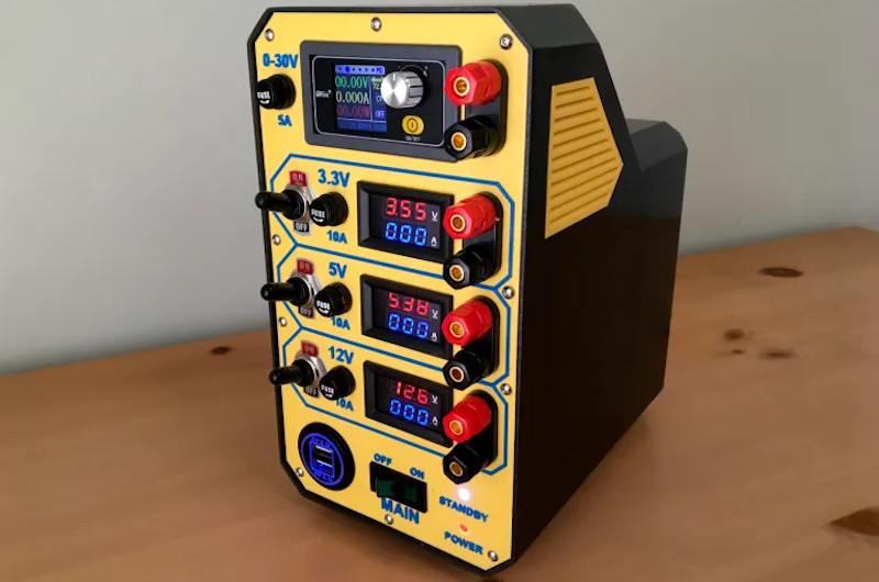
 As with your basic ATX conversion, this bench supply has outputs for 3.3, 5, and 12 volts. [Steve] has taken things a step further though, and given each one not only its own pair of banana jacks, but a dedicated switch, fuse, and LED volt/current meter. In addition, he’s added an adjustable buck boost converter that can output up to 36 V and features an attractive color LCD display.
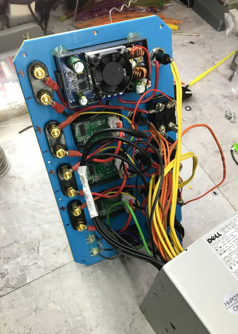
Everything is mounted into a sturdy 3D printed enclosure that’s large enough to give all the components and wiring some breathing room. The labels on the front panel were created with the classic pause-and-swap-filament trick, and go a long way towards making the project look like a commercial offering.
While this isn’t the first tricked out ATX PSU we’ve seen here at Hackaday, it may well be one of the most polished. Of course, even if you don’t need a new bench supply, there’s still plenty you can do with these ubiquitous pieces of hardware.


I made a power supply using one of those modules. I really like it. I used a printer ac adapter that provides 32v. The higher voltage should allow for higher amps. If I remember correctly, they accept up to 45v?
Made by Fischer–Price?
What does Poland have to do with it?
Polished not Polish, unless you were just being sarcastic…
It runs off of a sauerkraut battery
Was expecting 555 raspberry pierogis. Disappoint.
Delicious!
Pour Vodka on the contacts to shortcut the party!
why it’s not rainproof
Because it’s never rained inside my house… so I didn’t feel the need to make it waterproof.
I can see value for current sensing but why measure voltage on the fixed outputs? And a simpler approach to measuring current would be to measure it fr the OV line as that is common to all the voltages.
It adds flash. Maybe the meters are cheap enough that it doesn’t matter much.
I see Amazon sells a pack of five digital panel meters for about $20. I’m tempted to buy, and have no immediate use for them.
And those cheap meters display both voltage and current, so why not use both?
as the display shows, the output voltage isn’t exactly the specified voltage. Panel meters allow you to see what the actual voltage is, make it more obvious if you’re drawing enough that it droops, or if you’ve blown a fuse.
You can see if your fuse is blown :D
If you draw enough current, the voltage might not be what you think it is. Also these displays are cheap and show both so… There it is.
Google voltage sag. TLDR: As current draw increases, voltage decreases for most power supplies that haven’t got sag controllers.
If they have sag controllers, they better be quick or a sudden power draw removal can cause a voltage spike.
Call me biased but the 3d printed faceplate looks like a golden hammer solution…just using the usual panel technics seems more adequate to me, obviously, just taking of the panel, the box is a nice use of 3d printing…
Why 3D print the case? Why not use a conventional case making “techics” (should be “techniques”, BTW)?
The panel fits the case style. And for most people other methods are hard to learn and do right.
The only potential problem is the material used – if the PSU gets too hot, and case is made of low temperature plastic, like PLA, it can potentially met and cause fire hazard…
The usual drill and file an aluminium sheet seems more adequate for me than thick plastic, both for robustness and heat transfer, but well, it’s nice looking anway and doing the job…
Biased is probably the right word for that criticism, I agree.
I submit that if a person does have a 3D printer, and does not have the tools for the “usual panel technics” then they should just go ahead and use their 3D printer to make the panel.
OTOH if all you have is a hammer, everyone else looks like a nail… ;)
Polished?
The surfaces seems more like matte!
B^)
The faceplate says 0-30V. The article says it should have said 36V. So I guess that’s the module that was used, a 0-36V module.
But I thought those modules were step-down only. So, even if when plugged into a higher voltage source it should be able to reach 30 or 36V isn’t it actually limited to the input voltage minus some small voltage drop? It doesn’t do step-up does it?
The highest voltage out of an ATX supply that I am aware of is +12V. So with voltage drop I’m guessing the module actually tops out somewhere around 11.8 or 11.9V in this configuration. Am I wrong?
Some computer supplies did also have a -12V rail. I’m not sure they still do. So you could use that as the ground to achieve 24V but usually the current rating on the -12V rail is tiny. Also, then the ground terminal of the variable supply would be at a -12V potential compared to all the other grounds. That could let some smoke out of the item under test if the user isn’t careful!
I’ve looked at these modules and thought about building myself a new bench supply from them. This is where it always ends for me. First I think ATX supply (I have a shelf load of them) but not quite hitting 12V doesn’t do it for me. Then I think of using an old InkJet printer supply (I have a few of those too). But I still wouldn’t be able to use 1/2 or more of the range of the module which probably doesn’t matter as I rarely need more than 12V but it bugs me just because it does. Then I start pricing out a higher voltage DC supply to go with the module. And then I realize I’m getting into “might as well just buy it pre-made” territory. But my old, junky variable linear supply I bought from a college lab surplus sale still works….
There are LCD modules, less current.
Since they don’t need much, scrounge a small transformer and add a supply for the modules.
minus 12V, which I am unsure are still present were definitely low amperage… you’d definitly not bridge that with the +12V and get 24V at high amperage…
When the IBM PC came along, the RAM needed negative voltage. But that soon change, with the next density of RAM.
I suppose there may have been odd things that needed negative voltage, probably peripheral boards, designed in part because the voktage was there. But the big thing was RS-232, and that’s missing from most computers these days.
Yeah, definitely not useful anymore… I’m not even sure ATX specify it, just don’t bother enough to lookup… that said… 12V at bazillion amps like an ATX PS or 24V at may 500mA… seems like a clear choice, just get a converter…
some of the older disk drives used -12v with +12V on their motors. Gave the spinning platters a bit more oomph.
-12V was for RS-232 serial, which uses +- 12V signalling.
but… VGA anyone?
i always thought analog VGA needed negative voltage, no?
every time i forgot to wire it up; the vga output either breaks or just does not work,
one time, and i mean ONE time it worked with a VERY faint picture.
side note: you can adjust your contrast/brightness by varying the negative volts… serial and sound might suffer tho
negative is also used for sound-card, dialup-modem, some network cards (NOT ethernet AFAIK), and of course; (as previously stated) serial ports.
of course you wont have this problem if you have not yet upgraded to VGA
ya dont need negative voltages for MDA, CGA, EGA, or Hercules cards!
(Hercules being an oddity that could use an MDA monitor for MDA modes, but needed upgraded software/settings AND a Hercules monitor for the CGA-like modes)
It’s a buck/boost converter, so it can step voltage up and down. There will naturally be a minimum input voltage required for the device to boost all the way up to the top of the output range, but in the models I’ve seen, it’s usually only 6 V or so.
In the past, perhaps you were looking at outwardly similar models like the DPS3003, which are indeed step-down only.
That 36v is a buck/boost so only needs 12v in.
There are step up buck boosters that go up around 120v dc.
How are those voltages so far out of spec? I tested a bunch of ATX and older power supplies going back to 1995 a couple months ago, and not one was worse Than 5% out of spec. Most were better than 1%.
The PSU is within spec I’m sure, the 5 pack of voltage/current meters from China for $8 are likely not calibrated well.
@Pete
> The crooked display on the variable displays bugs the shit out of me
Yeah – me too!
Otherwise, a prety nice build. I like the honesty about the googling, and it’s a good simple write-up (which just so happens to already address many of the complaints that the above commentards are whining about.
Thanks, I’m pretty sure I wrote somewhere on there that I don’t know shit about electronics which is way I can’t even reply to half the comments :) I just figure out things as I go as I need too. I could probably just use a wall wart for most things I will power with this but making things is what I enjoy doing.
Nice work! Much better than mine!
I converted one. What a bother to work with all the wires.
Yep, a lot of unneeded wires to get rid of. I just put the banana plug jacks on the top cover of the supply. This guy’s creation is a beauty, though.
I would like to build one. Do I hav your permission?
People have been making these for a long time … go right ahead. I should have the files for my case ready to share in a few days on my website.
Beautiful work. My only objection is that, on “real” bench power supplies with multiple outputs, if they are presented in independent groups, they are usually actually independent, that is, galvanically isolated, not common ground like you you’d get from an ATX PSU. So the front panel layout is a little misleading.
Interesting project its homemade case is interesting now that maplin did the dirty on their customers by closing their high street shops amazon provides a lot of enclosures and electronic parts but making your own case saves money I like to use ex equipment cases for my projects and use as many recycled parts as possible to save money we have to spend our spare cash supporting the greedy gas companies now