Over the last several years, there’s been a trend towards designing ever more complex and powerful electronic event badges. Color displays, sensors, WiFi, USB, Bluetooth — you name it, and there’s probably a con badge out there that has packed it in. Even our own 2019 Supercon broke new ground with the inclusion of a Lattice LFE5U-45F FPGA running a RISC-V core. Admittedly, observing this unofficial arms race has been fascinating. But as we all know, a hacker isn’t defined by the tools at their disposal, but rather the skill and imagination with which they wield them.
So this year, we’ve taken a slightly different approach. Rather than try and cram the badge with even more state of the art hardware than we did in 2019, we’ve decided to go back to the well. The 2022 Supercon badge is a lesson in what it means to truly control a piece of hardware, to know what each bit of memory is doing, and why. Make no mistake, it’s going to be a challenge. In fact, we’d wager most of the people who get their hands on the badge come November 4th will have never worked on anything quite like it before. Folks are going to get pulled out of their comfort zones, but of course, that’s the whole idea.
A Virtual Retrocomputer
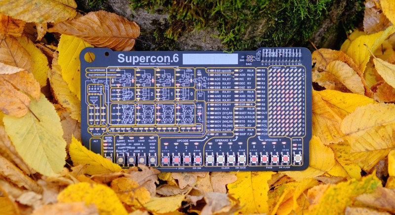
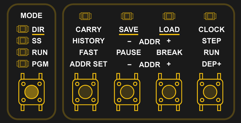
Those well versed in the history of desktop computing will likely find the front of this year’s Supercon badge strangely reminiscent. Festooned with buttons and LEDs, it’s designed to resemble the front panel of early microcomputers such as the Altair 8800 and the IMSAI 8080 made famous in War Games.
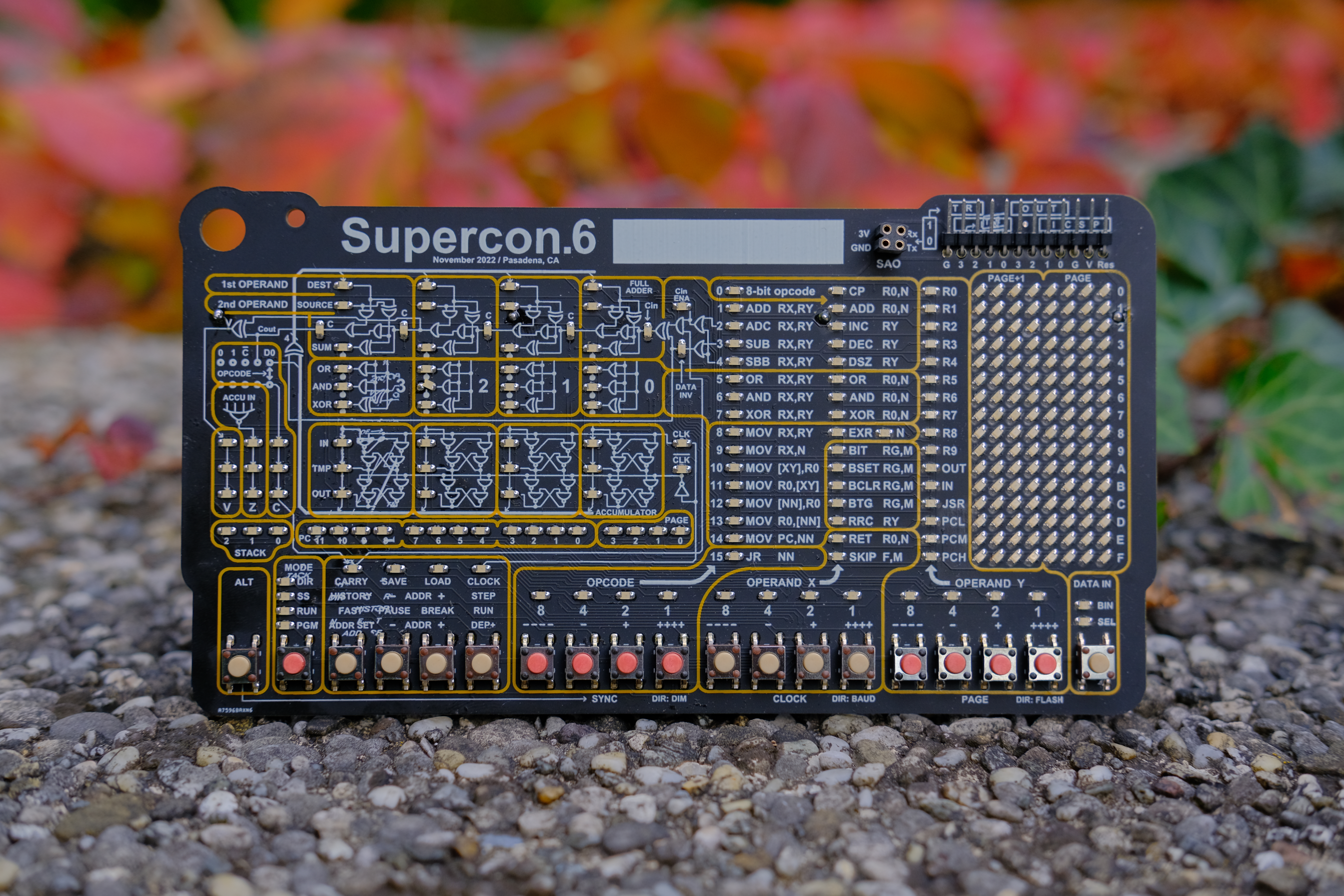
But the resemblance is more than just skin deep. The badge doesn’t just look like the front panel of an early microprocessor, it actually is. Well, a simulated one, at least. While the PIC24FJ256GA704 on the back of the badge is technically running the show, the user interacts with a virtual 4-bit processor designed by the legendary Voja Antonic.
Programs can be entered into the computer, bit-by-bit, using the row of tactile buttons on the front of the badge. Each 12-bit sequence, made up of an opcode and one or two operands, gets deposited into the memory address indicated by the program counter LEDs. If you make a mistake (and you will), you can step back and forth through the program counter to review and correct the instructions given to the CPU.
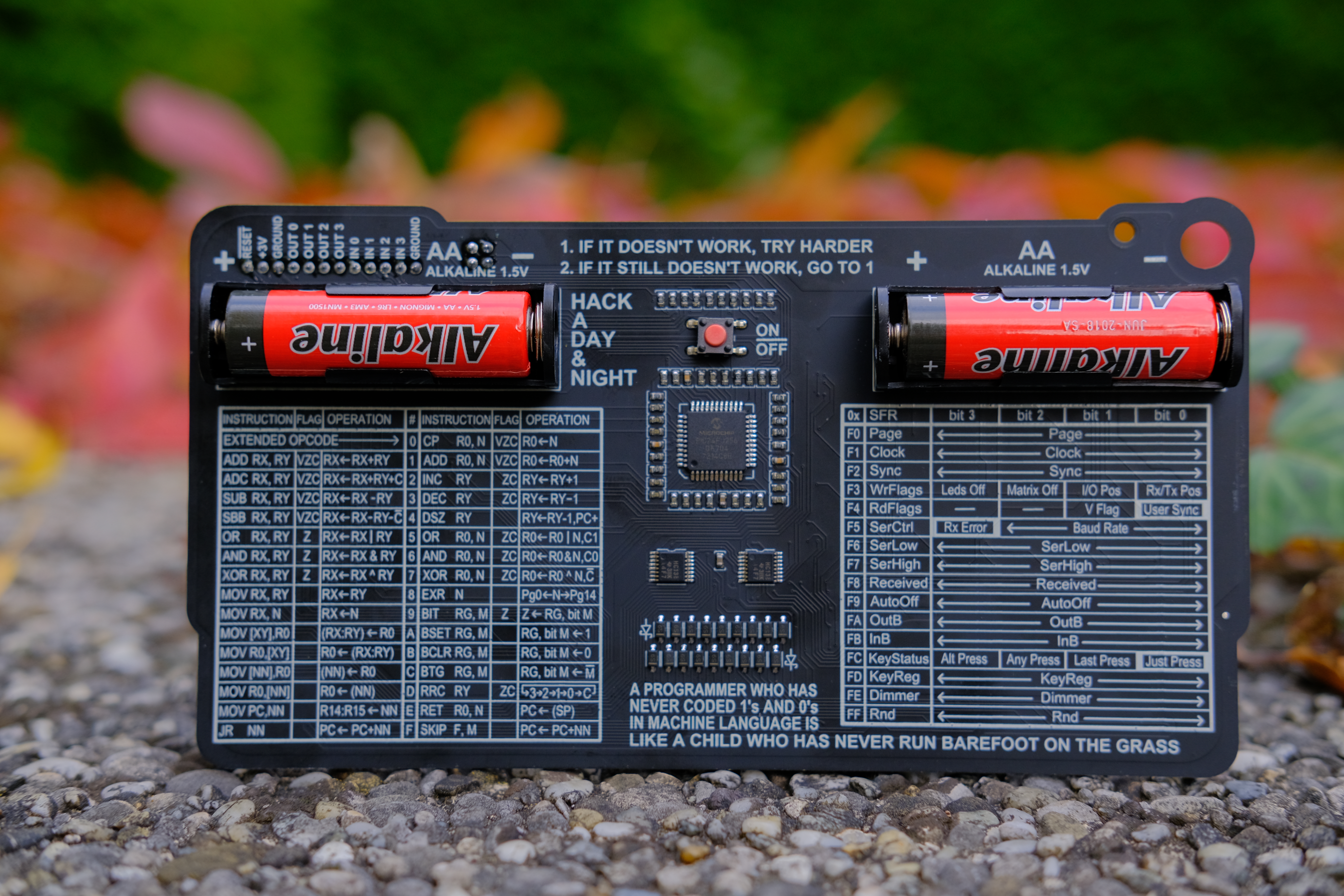
To help you out, the 31 instructions accepted by the badge’s 4-bit CPU are listed on the backside of the board. In addition, once you’ve entered in the binary opcode, a LED will illuminate next to the appropriate mnemonic on the front of the badge. While the silkscreen notes can’t compare to the exceptional documentation Voja has put together, at least you’ll always have a quick reference.
Programming is also made easier by the fact that all of the opcodes are between 4 and 8 bits in length. While a machine like the Altair may have required you to deposit as many as three binary sequences per instruction, the shorter opcodes mean there’s always enough space left over to enter the required operands simultaneously.

Room for Expansion
True to the early computers that the badge is trying to emulate, there’s not much in the way of onboard hardware. In isolation, all you’ve got for input are the physical buttons on the front of the badge, and output is limited to what you can show using the 8×16 LED array which provides a window into the CPU’s memory. A close examination of the documentation does reveal there’s a pseudorandom number generator you can poke around at, but don’t expect any more luxuries than that.
But don’t worry, we wouldn’t leave you without some room to grow. As you might expect from a modern electronic event badge, there’s a 4-pin Simple Add-On (SAO) header which lets you plug in various little gadgets and do-dads. The standard I2C data and clock signals have been replaced with simple UART in this case, but that shouldn’t break compatibility with most add-ons which do little more than pull power from the port anyway.
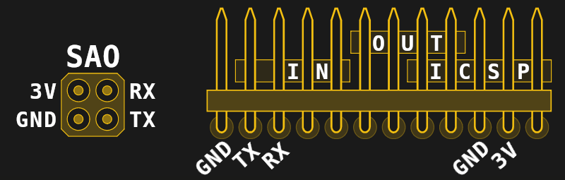
There’s also a dedicated I/O connector in the form of a 12-pin standard pitch header along the top-right edge of the badge. This header shares the UART TX and RX pins with the SAO connector, but is capable of quite a bit more. For one thing, it serves as the badge’s In Circuit Serial Programmer (ICSP) interface should you want or need to reprogram it. But more interestingly, it offers four input and four output pins that can be accessed in your programs by reading and writing to the appropriate memory registers.
Sharing is Caring
Badge hacking is a big part of the Supercon experience, and over the three day event, we hope to see all kinds of interesting software and hardware developed for this faux-retro computer. Given the relatively short amount of time you’ll have, teamwork is strongly encouraged — don’t be shy to ask other attendees what they’re working on to see if you can lend a hand.
Of course, collaborative development is a bit difficult if the only way to share your code is by scribbling out binary on pieces of paper. While you’ll have our eternal respect (and perhaps even earn a special award) if you manage to accomplish something substantial on your badge using nothing but the integrated peripherals, we’re not so evil that we’d make you do it that way.
 As such, the UART pins on the expansion port can be used to upload a program from the badge to your computer by way of a standard USB-to-serial adapter. With the adapter already connected, you simply need to put the badge into
 DIR (Direct) mode and press the SAVE button.
This will cause the badge to immediately start spitting out data, so you should already have your receiving side setup and ready to go before pressing the button. On a *nix machine that would look something like this:
cat /dev/ttyUSB0 > out.hex
If you press the LOAD button, the process works in reverse. A hex file sent from your computer will be loaded into the badge’s memory where it can be immediately executed. In this way, a program that was entered by hand into one badge can be quickly backed-up and distributed to others. It also means that if you formatted it appropriately, you could write the code on your computer and simply send it over to the badge for execution…
Incidentally, while the badge can only have one program loaded at a time, up to 15 can be stored to the onboard flash. This is accomplished by first holding ALT and using the OPERAND Y buttons to cycle through the available storage slots, and then with ALT still held, pressing either SAVE or LOAD. With this technique you can keep your own personal programs safely stored away while you experiment with whatever hot new hex is making the rounds.
Get Your Hands on One
Now, the best way to get one is to buy yourself a ticket and come join us at Supercon. But if you just can’t make it, we understand. We’ll be releasing the Gerbers, a full badge emulator, and the code for the PIC soon, so stay tuned.


OMG. This may literally be the most lovely thing I’ve ever seen.
As far as badges go yes, I agree, in fact it is the first badge that has ever triggered “Me want!” feelings in me.
+1
I would love to have one too! I wonder if they would sell them to us dirty peons who can’t attend…
Yea, I’d love one too. I wish some of these conventions would offer a badge only deal. Maybe it will appear on Crowdsupply
I’d like one too. I would like to make my own PDP 8 or 11 MP.
What, the 4004 wasn’t good enough for you? :-)
Have you tried getting them during the Great Parts Shortage™?
I thought the cool kids were fabbing their own these days.
Or has that not happened yet? Quick, what year is it?
This guy is working towards it – https://www.youtube.com/watch?v=IS5ycm7VfXg
I was all ready to start designing a an adapter to solder all the button pins to a controller to program automagically till I saw you can just upload over uart :P
{sarcasm} What, no 555 timer? {/sarcasm}
Making it a 555 is an exercise left for the student.
B^)
eww, its CISC!
What? This is very ‘RISC’-like in design.
well one can argue that 16 opcode on a 4bit instruction bus is not really reduced…
It’s funny you should mention that. ‘RISC’-style instruction sets have historically had a lower encoding density than their ‘CISC’ competitors. It’s just the price you pay for having lots of registers and needing to encode your source(s) and destination in every instruction.
‘CISC’-style instruction sets, on the other hand, tend to use a lot more implicit sources and destinations, allowing for common instructions to be encoded in a single byte.
It wasn’t really until memory started to become cheaper that ‘RISC’-style instruction sets rose to popularity.
Funny, you’re both talking reduced. Reduced: number of available instructions. Reduced: memory length of instructions.
But can it run Doom?
question is it run fuzix ?
Given enough memory, the virtual CPU surely can. Don’t ask for how fast the game runs but if it’s a touring complete CPU you can run everything on it.
Just add some “smart” “virtual memory” which updates the flash memory with the next block of code to be executed (this assumes that the memory is not reset when a new chunk of code is uploaded). Then run Doom in 8×16 pixel glory at a very low fpm rate. Until the batteries die. Which is, probably, before it has finished drawing even the first frame, so better ad an external power supply as well.
Nope, “fpm” is not “frames per minute”.
It’s “frames per month”.
Just in case you get any funny ideas: yes, Doom has already been ported to devices with e-ink display. You might ask YouTube for “Play Doom on an E-ink screen”. More than an 8×16 pixel screen resolution, though.
They didn’t ask for how fast, but in theory every touring machine can run Doom or Crysis, just wanted to make a point.
For the device in hand, if one can make a simple VM inside the code limit that can access 16 MByte of serial SRAM and run something more complex from that then yes, you can run Doom. Nothing that will beat any speed records but still, Doom running on the badge. :)
The original doom was about 4MiB of RAM and 40 MiB of harddisk space and a 386 or better. So with *ponder* maybe if you networked 4 of them you could run everything from a RAM drive … But it would be near impossible to get your hands on that many badges for long enough to debug *ponders some more* …
(ref: https://i.redd.it/vtswj6s8wh321.jpg )
>The original doom was about 4MiB of RAM and 40 MiB
The shareware WAD is ~4 MByte with the release WAD shy of 11 MByte and would fit easily inside a 16 MByte serial flash together with your code. Add 16 MByte PSRAM and you should be fine.
4k 12-bit words should be enough for a simple VM that emulates some more high level CPU (RISC-V?), other people wrote whole DOS style multitasking OS into 8k words back in the days and BASIC interpreters, not far off from what we would want to do here, in 2k.
Rough idea, VM Code is always executed from PSRAM and on boot the VM reads the first 512 bytes from the flash into RAM and executes it.
All IO it emulates is a serial connection and flash access. The CPU sees 16 MBytes of PSRAM, for simplicity sake no caching, brute force read and execute from said PSRAM. Slow as molasses but does the job.
Hang on, I have questions:
1. What’s the clock speed? No really, I need to know this for things like bit bang interfaces and such
2. How many instructions can the memory hold?
3. The stack is only 3 deep? Hummm… have to figure out how to implement a stack in RAM.
1. The clock speed is selectable in 16 steps from 0.5 Hz to ~250 KHz (plus single step). However, the highest clock is not synchronized (so timings are not guaranteed), but performed without sync delay. The highest synchronized clock is 100 KHz (0.1 MIPS).
2. The program memory capacity is 4096 instructions, 12 bits ea. Data memory is 256×4 bits.
3. The stack is 5-deep (3-bit stack pointer). Stack is already in RAM, page 1.
(you can download PDF manuals from the project page https://hackaday.io/project/182568 )
At last your project has been released !
As much as I would have liked to have seen an AND!XOR style badge with all the bells and whistles, I 100% agree that it turned into a bit of an ‘arms race’. The advantage of those more complicated badges, is that they came all ready to go doing interesting things. I’m sure this will too, but it will force people to be more creative with the hardware limitations. One of my favorite things about Supercon is coming home with hardware goodies to study and hack on over the next year until the next ‘con (I’m slow, yes it takes me a year to go through it all and enjoy it lol..).
I REALLY hope they have hardware workshops again this year, and maybe one for the badge for those who aren’t as familiar with the concepts (like me!).
Dates/times not yet firm, but badge workshops tentatively scheduled for Friday afternoon and Saturday…sometime, probably also afternoon.
Oh, I love that this is designed by Voja Antonic. I had the pleasure of speaking with him at a previous Supercon when he designed those orange cubes that could talk to each other :) Not only is he a great hardware designer, but he’s a swell guy, and his talks are amazing. Is he going to be here this year? Either way, thanks Voja! (and everyone else who worked on it :D)
Not sure if my previous replies made it through, but I’m really excited about this years’ badge, and that it was designed by Voja Antonic! I had the chance to meet Voja a few years ago at Supercon and got to talk with him about the orange cube he designed (which was a really unique little piece of hardware!). He’s a swell guy, and an amazing hardware designer. Thanks Voja, and everyone else who worked on this badge!
I am really looking forward to the badge-hacking day, and I hope there is some discussion or even maybe a mini-workshop for it :)
This is boss! Thanks Voja :)
Tell me about the two color solder mask!
Looks like a two-color silkscreen, to me… applied atop the soldermask. Good eye, hadn’t caught that.
Nice attention to detail!
You’re right, I meant silk screen! I wonder which factory offered to do this??
PCBGOGO did it correctly. You have to contact them first and explain which PCB layer should be considered as the second color (could be any unused layer). And of course, pay a little more. Respect, PCBGOGO!
Before that, I sent a lot of emails to many PCB companies, and only two of them replied that the 2-color top overlay is doable. My first disappointment was JSDPCB, who did it with white+red silkscreen, but the red paint was transparent (!) and thus invisible against the black background. Unfortunately, no other colors were available.
The second one was ALLPCB, who delivered the same transparent red, but without white at all, so the result was nothing+invisible on the black solder mask! Lack of white was a small production error, they said, we will fix that… No thanks, just forget it!
The similar result with the same error from two companies gave me the idea that some Chinese PCB companies do not exist as producers. Could it be that it’s an one-man company which just receives your order and transfers it to some master PCB lab?
This whole area of computation is very interesting from the viewpoint of computer security and reliability. Using severely cut back instruction sets means that the programs can be mathematically proven to be correct, with no buffer overflows. no uninitialized memory, etc. Way beyond what even valgrind can do. Very useful for drivers etc that require minimal functionality and need to stay in their lane. With today’s super fast and capable processors it is no big deal to emulate an instruction set.
Whatever you say. I think you’ll find that programs for cut-back processors of this kind are typically harder to verify, because programmers wind up needing to pull out every trick in the book to get good performance, self modifying code included.
It’s a bit hard to pull off self-modifying code with a Harvard architecture, but for a modified Harvard arch or von Neumann system all bets are off.
In older systems (1960s and before) you often had mathematically proven correct code given the hardware in use at the time. It’s one thing to burn a PROM for every code change or have to create a new set of punch cards and re-feed them into the system, it’s quite another to open up the machine and modify the core rope memory, TROS, or diode matrixes.
And the first thing I see when I look closely at the pictures is the crooked LED off-pad in the #2 block (middle) :)
(Since I can’t edit, it’s a beautiful badge btw)
Oh great, now you’ve got me seeing it…
B^)
Solder fixes everything!
I was just going to point that out.
I can’t tell in the pictures, so this is a guess, but it may be off center as to help with quick visual id of a different gate out put type. The picture looks like the 3 gate are different input to an output. or I’m just wrong, anyone feel free to correct me . I didn’t do a lot of research on the badge just yet. However I know I want one. This person could do a small batch run maybe create a small book with it and monetize on it and reinvest those profits back into the community or projects or as they choose.
You are right, some logical states are formally wrong in some cases. The schematic is greatly simplified, good for rough reference and principles only. A much larger area would be required to represent the correct logic and, in particular, the data path. For example, not all instructions affect the state of the accumulator or flags, but the enable logic is omitted. Also, the 4-bit XOR circuit that serves as true/invert logic (below the Cout line from the adder) should not be on the DEST but on the SOURCE bus, which is not represented at all. This one would be good for SUBR instruction, but it does not exist here.
There is another formal inconsistency – there is no accumulator in the processor, but 16 selectable GP registers, which are memory mapped. Therefore, the accumulator in the schematics should be actually considered not a single register but a flexible destination, which depends on the context of the instruction. Imagine the schematics that represent the correct write logic and data path.
This is just a badge, which is too big anyway, so compromise was inevitable.
Love this badge, i have the fine propouse of assisting SUPERCON next year, but i really hate to miss this year badge. Please someone make more and put them on Tindie with international shipping. PLEASE.
This badge is so cool. Is there any way to get one shipped? Or a way to get one before the conference with a ticket?
I ask again,
“Will it be available on Tindie in the near future? ”
B^)
Before the con? We’re not giving it out until the doors open.
There may be an emulator and assembler coming out in a week or so that’ll let you play around with it virtually. Stay tuned.
Tindie sales after the fact? Can’t rule that out, but it’s a lot of work — there _have_ been a number of asks. Either way, the design files will all be released, so it’d be easy enough to do a group buy.
Can the SAO connector drive an LCD or OLED display?
Just curious.
It looks like it could with some programming. Most of the small LCD/OLED displays support I2C. Although the writeup says the pins are mapped to RX and TX instead of SDA and SCL, it looks like they could be reprogrammed to be whichever you want (based on a quick look at the MCU datasheet).
“Folks are going to get pulled out of their comfort zones, but of course, that’s the whole idea.”
Hopefully not so far as to miss the talks…
B^)
I definitely want one of these badges. Almost considered buying a ticket but not going to the conference, just to get the badge, but alas, the $128 early bird tickets were all gone. Let’s band together and make some. Tapping the original vendor(s) would be the ideal route.
Ahh man this looks so awesome! Another reason to be sad that I can’t go this year. :( Count me in for a group buy though to make them ourselves!
Great job !!!
4 bit deep learning?
https://medium.com/swlh/4-bit-deep-learning-d1614c0883e3
ooooo! That is SO lovely!
So.. the badges are sent out beforehand and the attendees use the time to program or mod their badge to do something interesting and then show off what they did when they get there?
Is that how it works?
Cool!
Wait a minute… Doesn’t the use of a PIC make this just another computer board with fancy LEDs, pushbuttons, and nice silkscreen legends? I’m impressed by the artistic aspect, but not by the technology. Years ago I tired of pushing buttons and loading code one bit or byte at a time. It’s just so ’70’s. Students will get more useful information about computer-circuit design and architecture from the book, “Code,” 2nd edition, by Charles Petzold. The author uses an 8080 as his model. And the book probably has a longer life and needs no power source.
fuzix can run on this?
Very nice
Please don’t hold out to it as a superconductor exclusive, This looks like a cool learning aid!
Gerber, BOM, Design files have been released (Thanks Voja!) at https://hackaday.io/project/182568/files. I’m eager to learn and make a hooky version of this badge, but I’m also new to the PCB manufacturing world. Anyone have experience with the whole process? Better to group buy? Have the shop assemble?
I appreciate any guidance!
Generally just going for a “Prototype PCB” service suffices. Either a domestic PCB service like say OSHpark or Eurocircuits. or one of many chinese fab house services like Elecrow. Whether they offer assembly varies.
This shouldn’t be a difficult board to either self-assemble or have assembled as it doesn’t have many different parts. It is mostly just a lot of leds, schottky diodes, a PIC microcontroller and a pair of multiplexers. Only the multiplexers seem annoying to solder by hand being TSSOP-16 packages and the leds can be a little tedious.
Regardless though. You will likely have to program the PIC controller yourself.
Thanks for the response Foxhood! Since I posted that I did a bunch of researching and tried to see what it would take to put the badge together myself. I reached out to the original fab, PCBGOGO and found out why you would want to do a group buy. If you’re like me and don’t have an easy way to solder all of the components and would rather just get it assembled, it’s gonna cost you a bit due to the Minimum Order Quantity, not to mention supply chain issues are making the PIC24FJ256GA704 hard to find right now. Even some of the passives in the BOM aren’t available to ship immediately.
In the end I decided to get the minimum 5 boards and some alternative parts. I couldn’t find the PIC24FJ256GA704, but I did manage to find a couple of PIC24FJ128GA204s on Ebay. After taking a look at the firmware that Voja made for the badge, I figured it should still fit in the 128kB flash of the 204. I also saw that the pin-out matches the 704. I’m hoping this cursory investigation was enough and I can get it to work, but I’m sure there will be some hurdles I didn’t consider.
First time I’ve ordered a board from a shop, so it’s been an interesting learning experience especially during these times of tenuous supply!
Did you manage to get this to work?
Hey, Watchmaker I didn’t get this working. I threw my plan out on the project page, https://hackaday.io/project/182568-badge-for-supercon6-november-2022 and Voja so kindly saved me some headache by telling me upfront that the PIC24FJ128GA204s I have won’t cut it.
Hey everybody. I was one of those people that missed the con, but managed to order some parts and pcbs and get one of Voja’s brilliant Supercon 6 badges made. I have parts for a few leftovers and thought I could sell them as kits. If anyone’s interested you can find them on my eBay store at https://www.ebay.com/itm/204227182417?mkcid=16&mkevt=1&mkrid=711-127632-2357-0&ssspo=QBrvzZS3R5-&sssrc=2051273&ssuid=QBrvzZS3R5-&var=&widget_ver=artemis&media=COPY. Mind you they do not come with the PIC as that is still impossible to find it seems, but if you’re lucky enough to get one, this will be everything else.
Hi,
I am planning on building some of those for me and my geeky friends. I have enough experience soldering 0603 and tssop so that doesn’t bother me. However I am not sure on the proper way to flash the firmware, so some guidance on this will be appreciated in order to decide if I should go with project.
My concern is that probably the factory PICs won’t come with a bootloader, so the firmware flash procedure from the manual won’t work?
Thanks!
Hey Lavrentii,
I’ve successfully flashed one of these and can attest to the fact that it’s not only possible but actually pretty easy.
1. First thing’s first I would make sure you have a programmer to program the ICSP port of the badge. You can find a reference in the https://cdn.hackaday.io/files/1825687810989312/5%20Hardware%20Rev4b.pdf. Personally I used the MPLAB SNAP programmer/debugger https://www.microchip.com/en-us/development-tool/PG164100 and connected it just like in the hardware reference manual illustration.
2. Next download and open up the MPLAB X IDE and import the binary hex file provided in the firmware flash. Connect your programmer and you should be able to go ahead and flash it to the PIC on the badge. (I used this video for reference: https://youtu.be/obvUr5jKaXA?t=1348)
3. Profit!
I believe you’re correct in that the factory PICs don’t come with a bootloader. If I’m not mistaken the new firmware .bin update file that Voja made is made to update to the Berlin firmware and can be done through USB/UART if you have a badge with the old firmware, because the old firmware has a bootloader builtin. If it’s a fresh PIC, however, you’ll have to flash the .hex file that’s in the firmware project. I feel like once you finish the soldering, the hard part will be over and this will be a breeze.
Thanks a lot for the detailed explanation!