The inner orbits of the Hackaday solar system have been vibrating with the announcement of the 2022 Hackaday Supercon badge. The short version of the story is that it’s a “retrocomputer”. But I think that’s somehow selling it short a little bit. The badge really is an introduction to machine language or maybe a programming puzzle, a ton of sweet blinky lights and clicky buttons, and what I think of as a full-stack hacking invitation.
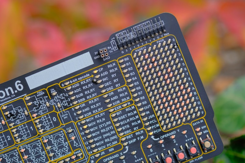
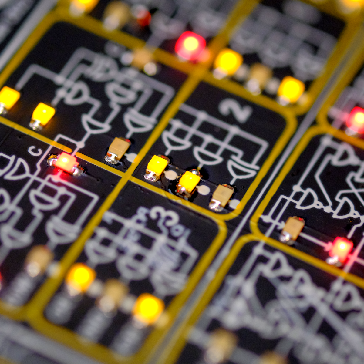
Voja Antonic designed the virtual 4-bit machine that lives inside. What separates this machine from actual old computers is that everything that you might want to learn about its state is broken out to an LED on the front face, from the outputs of the low-level logic elements that compose the ALU to the RAM, to the decoder LEDs that do double-duty as a disassembler. You can see it all, and this makes it an unparalleled learning aid. Or at least it gives you a fighting chance.
 So why would you want to learn a made-up machine language from a non-existent CPU? Tom Nardi and I were talking about our experiences on the podcast, and we both agreed that there’s something inexplicably magical about flipping bits, calling the simplest of computer operations into action, and nonetheless making it do your bidding. Or rather, it’s anti-magical, because what’s happening is the stripping away of metaphors and abstractions. Peering not just behind, but right through the curtain. You’re seeing what’s actually happening for once, from the bottom to the top.
As Voja wrote on the silkscreen on the back of the badge itself: “A programmer who has never coded 1s and 0s in machine language is like a child who has never run barefoot on the grass.” It’s not necessary, or maybe even relevant, but learning a complex machine in its entirety is simultaneously grounding and mind-expanding. It is simply an experience that you should have.


I was offered a free ticket to the supercon 2022 and was sorely tempted to accept the invite just to get the badge. I wonder if I can give my ticket to someone else and make it so that they send me the badge? Or maybe just send me the badge without the fuss and bother? I could have asked this privately, but I bet there’s others who cant afford the air fare who also might want this ‘must-have’ gadget.
Alternatively, maybe send me the airfare and hotel costs?
You’re in Britain, right?
B^)
I live on an island in Wales, UK. Next year, I propose the conference can be held on my lawn. I can supply a certain amount of free home made cider.
You’re in the same hemisphere as the conference so you’re one up on me. The cider sounds nice. I used to make Turbo Cider long ago, turned out great.
I’ll go for you.
I live in Glasgow ; can I buy one?
I’d love to get such a badge. But as usual, it’s for participant only. I wont fly through atlantic to attend a (probably rather interesting, granted) fare, just to get the badge.
Sure, the conference will certainly be interesting, but even with cash to burn there’s also the time and hassle in traveling, wasting precious days of my life loitering in airport lounges and cramped up in aircraft. If I’m quite honest, I just want the badge.
This is Hackaday.
Make your own…
Good point. I think I’d have to go one better and try and build an ACTUAL 4 bit computer rather than emulated. Where to start?
Or build a real Texas Instruments GPL CPU. That’s Graphics Programming Language, not GNU Public License.
The failure to make their GPL CPU work is why TI shoehorned their TMS9900 (with some alterations and renamed TMS9995) into the otherwise 8 bit 99-4 and 99-4/A Home Computer.
This :)
All of the files will be available, and I believe there are services that can even place the SMD parts for you.
I’ll start on a coding idea using the docs beforehand. I haven’t coded in 1’s and 0’s (or more precisely, 1’s and 0, 2, 3, 4, 5, 6, 7, 8, 9, A, B, C, D, E, F’s, so there’s yer abstraction) since 1995.
Last time of 1s and 0s was 1997 for me. Raw hex is still occasionally used…
I thought I read on Hackaday years ago about a cardboard computer.
IIRC a contraption that had cutouts and sliders to simulate the inner workings of a simple processor.
A quick search did not uncover the article.
Just a possible way to get started on the bodge badge.
B^)
There was more than one kit or book for a computer made out of paper in the sixties. I know there’s been an article here, but have no idea when.
I believe you are referring to the Cardiac. I actually had one of those back in the 70s. :-)
I actualy taught classes using Cardaiac in the early ’70s. Students really “got” how a computer worked…or they quickly dropped the class.
Check out https://www.instructables.com/CARDIAC-CARDboard-Illustrative-Aid-to-Computation-/
That is probably what I was thinking about.
Back in college, I worked out a recursive function on paper before coding it (write this number to the stack, increment the register, next step, pop from stack, blah bla bla…)
Hard to do (for me) but it helped me to understand what was happening.
I didn’t know about the cardboard computer, but my Digicomp I is missing one part.
And there was a book “How to Build a Working Digital Computer” that described making one with paper clips and knife switches, a lot of wire, and flashlight bulbs. The program was stored on a drum covered with masking tape, with holes cut for the 1’s.
Still have it. An article on it is here:
https://www.evilmadscientist.com/2013/paperclip/
As for computers with front panels, I have a PDP-8e, but no teletype for it.
Just use a computer with a serial interface, and terminal software. My i7 has a serial port, and I think minicom is still in Linux.
The serial board for the PDP-8e uses a current loop, not RS-232. Probably can make an adapter. And then an image of an ASR-33 teletype reading and punching tape would be a nice touch, including the noise!
Could make a game of it by having it randomly tear the paper tape. Back in the day, there was Mylar tape for tapes that were used a lot, such as boot loaders.
I looked it up – USB to RS-232 adapters are readily available and cheap; current loop to RS-232 are over $100. Probably would build one instead.
But I’d have to fix the PDP-8e first, as it has at least one stuck bit at the backplane; probably dirty from being in the basement too long. And I haven’t even tried the serial interface board; it looks modified and may not work properly.
Yes, IIRC minicom is still available in Linux; had to use it at work recently.
Although for testing, my VT-100 might have a current loop adapter already. (Yes, I have several antique devices.)
The serial board (M8650 IIRC) for the Omnibus on the PDP8/e,f can do both Current Loop and RS-233 serial depending on how it is strapped and the cable used. My 8/e has 3 of them, 2 configured for RS-232 and the third for Current Loop and 110 baud for connection to my 33ASR Teletype.
Two transistors and a few resistors. Or if transistors scare you, one comparator and a couple resistors. Heck, one reed relay.
Current loop to RS-232 adapters were commin back then. I think one is even in the KIM-1 manual. So
I don’t expect a problem.
Haven’t done hardware in a while, but it will come back. Once I have time for the project.
Thanks, everyone.
Old comms board designer here. Current loop to RS-232 is easy and should cost you less than $20. You’ll need a pair of optocouplers and a MAX-232 (possibly some buffer gates to increase drive current.
PDP-8 TX side: transmitter is going to be a switch. Simply put the TX in series with a 20mA source and the diode of an opto coupler and use the output of the optocoupler to feed the TTL input of a MAX232 transmit side, which goes to the RX input of your DB9.
PDP-8 RX side: it’s going to source 20mA current, you need to switch it. Use an optocoupler again, but this time, it’s the transistor side that connects to the PDP-8 RX input. Make sure it can handle 20mA through the transistor (many can’t). The LED side of the optocoupler goes to the TTL output of the MAX232 receive side, and the RS232 input of that MAX232 gate goes to the TX pin on your DB-9.
Cautions: make sure polarities match, and you may need to put a buffer between the MAX232 and the optocoupler LED.
Also: Googling “current loop to RS232 schematic” produces these…https://wiki.theretrowagon.com/wiki/20ma_current_loop_to_RS-232_conversion
And again, thanks, especially Michael Black. I think my serial interface board was modified not to source the current. Fortunately, I have the full set of schematics for the PDP-8e, including for boards I don’t even have (and I have a lot – the people discarding it let me take a lot of random PDP-8e boards they had, and their prints. That company is now long gone – you are free to guess what company it was, but I won’t confirm or deny which one it was.)
The paperclip computer was a computer in that it could do calculations if the operator correctly manually manipulated all the switches.
What it was not was an *automatic* computer. I was going to build one until I figured out that turning the program drum didn’t actually do anything but turn light on and off! The lights are merely prompts to the operator to open or close switches. Then the operator must turn or flip or slide other switches to work the program through the rest of the device.
I understand that it’s intended to provide a literally hands on example of how a computer manipulates data, by making the operator do the manipulation. In other words it’s an electric abacus, not what used to be called an automatic computer back in the day – to differentiate between devices that human computers used to aid them in complex calculations and non-human computers that could be programmed then run the program unattended or automatically.
What would be an interesting project is to take that design and make it a true automatic computer so that rotating the program drum triggers solenoids to open and close the RAM switches, and running the program operates solenoids and motors to flip and slide switches and rotate BCD encoders.
Design that upgrade then do a new version of the book “How to build a working automatic digital computer.”
The one thing I found to be especially nifty in that book were the hand built rotary BCD encoders. Everything except the incandescent light bulbs in that design is hand built from wire, nails, screws, bit of metal, and wood.
Thanks to 60’s Vintage Bits for the info on the serial board. Mine has the current loop cable.
Make a 4-bit computer out of Logic Goats!
https://www.robives.com/project/logicgoats/
computer must have disc, screen (ok is memory pages), keys (meybe mechanic low profile) and network (meybe irda or rs232)
when i coding long program (input 1h) i need correct my program simple.
meybe irda and photo diode for reading barcode?
Okay Sir Elliott,
I am not seeing the connection you hinted at few months ago about an encryption in the SuperCon logo and the badge.
Of course, encryption beyond Rot-13 escapes me.
P.s. sorry about adding the 2nd “t” in your name.
P.s. 2, by ancient tech, I thought this article was going to be a continuation of the “Publish or Perish” article.
And if was really on ancient tech, maybe about the Antikythera mechanism
https://en.wikipedia.org/wiki/Antikythera_mechanism
I hope to buy/assemble one of those someday. But the idea of cutting brass circles and filing teeth is more time/effort than I’m willing to commit.
Sorry for the misunderstanding!
There was no “encryption” — just the blinking-array-of-LEDs style in some of the early Supercon art was taken from the badge. I think it even had the hex labels on the side?
No secrets, though. Apologies.
No worries, I probably read it wrong.
“A programmer who has never coded 1s and 0s in machine language is like a child who has never run barefoot on the grass.”
Nice analogy, though I’d rather associate Assembly Language with grass.
“1s and 0s” feel more like walking on pebbles, whereas hex feels like running on rough sand. ;)
Which programming language is like running barefoot on razor blades?
Java, PHP, Lua, JavaScript…
“You’re seeing what’s actually happening for once, from the bottom to the top.”
Transistors all aglow.
If your transistors are glowing, you’re doing it wrong?
Even after trying to dissect what is happening under the hood, it is still a damn cool badge.
Looking at the back and the front of the PCB, there are:
20 GPIO pins for the 20 buttons.
272 LED’s for the display.
It would take 17 pins to drive 272 LED’s using Charlieplexing ((n*n)-n).
But there looks to be two 3-to-8 Line Decoder chips on the back.
So 7 GPIO pins from the MCU are being used to drive the display.
Never mind, found the documentation: https://hackaday.io/project/182568-badge-for-2020-supercon-years-of-lockdown
24 GPIO pins in total – wow. I guess it is time to start unlearning some things.
There’s a complete schematic diagram in the PDF “Hardware”.
https://hackaday.io/project/182568
I’m working my way through it now. Thank you – great badge, I love it when I see something that is new to me.
I’m hoping the PCB files get added. Maybe after the conference, others could do a batch order.
PCB files and BOM will be published tomorrow.
Source and HEX files for firmware too.
Hackaday should offer another color version after the event. I want one. It is my understanding that maybe they will release the Gerber files. Just put some boards on Tindie and they will fly.
My kingdom for a card reader to serial
If you find one, I can still unjam and change the ribbon on an 029 keypunch.
Somewhere I still have a box of cards with my old high school programs (for an IBM 1130)
I should retire to the Living Computer History museum as an exhibit.
So, who knows what “face down, 9 edge first” refers to?
Me. Load that card hopper.
Back in the early 1970’s, there was a poem “The Last Bug” in a Decuscope magazine (from the DEC users group DECUS), that had a programmer slaving to fix the last bug, using core dumps, etc. At the end, “He died at his console of hunger and thirst/They buried him one day, face down, 9 edge first”.
And I have spent much time unjamming a 1442 card eat crunch (OK, IBM called it a Card Read Punch)
Oh man do I want one of these now! This is so awesome! Seeing things visually at this level is really fun. These could make excellent learning tools for teaching kids (and adults, of course) how processors work at the lowest levels.
That’s absolutely beautiful. I hope someone starts making something like this for normal retail. Maybe Hack-a-day should talk to Adafruit about selling something like this. I would totally buy it. In fact, I have kids, so I would be willing to buy several!
Take the book “How to build a working digital computer” then modify the design so it runs itself instead of relying on the operator to do the actual data manipulation, then do a new version of the book detailing the upgrade as “How to build a working automatic digital computer”.
While I sulk about the fact that such coolness is only available to attendies, I’ll mention that as a kid I had a “digital” lab thing that used essentially ginormous slide switches, lights and protoboard-style sockets, and after several minutes of wiring, then finding the mistakes and trying again… you’ve simulated a NAND gate… whoopee. I was similarly underwhelmed by the kits that had a couple of DIP TTL quad gate ICs. I guess that I found basic logic gates to be easy to understand.
I wasn’t really challenged and excited by digital electronics til I got my first computer board – an RCA COSMAC VIP (CDP1802).
Back to sulking. Get offa my lawn.
I trained on a PDP/8e and one of these. I guess you can still find them on eBay and such. https://www.worthpoint.com/worthopedia/heathkit-et-3400-microprocessor-1885121264
Those are neat! I was in Argentina a few years back, and met a teenager who was taking an engineering course, and had a KIM-1, similar to this.
This is really cool!
Any chance that it would be made available for purchase by the general public? It could have some modifications made or be solder masked a different color to keep the exclusivity of the originals.
Failing that, could we have an emulator that runs on Android / Apple tablet?
Personally I’d like to see a half-scale Curta calculator in emulation, maybe worn as a large pendant.
Elliot, please make some extra for sale. I’ll walk all the way to Portugal to buy one.
Or, even better, give some away on the what’s that sound.
BTW, I was so bummed. I knew it was a floppy as soon as I heard it but Thursday morning the form was not working already :o(