With modern microcontrollers, the process of interfacing with the analogue world is easy. Simply enable the on-board DAC or ADC, and talk to the world. If you’ve ever done this with a slightly older microprocessor, you might have encountered the DAC and ADC as chips in their own right, but how about the earliest generation of microprocessors? In those days, if an analogue component was needed, the circuit which would later be integrated on chip would have to be made from scratch. So it is that [Florian Wilhelm Dirnberger] has built a very old-style 6-bit DAC, using a circuit that would have been familiar back in the early 1970s.
At its heart are a pair of 4007 triple CMOS inverters, which form the six bits driving a resistor ladder DAC. This is simply a chair of R… 2R resistors, relying on Ohm’s law for its operation. Each successive bit contributes twice the current to the output of its predecessor, and the 4007 simply provides a buffered supply for the bits.
It’s the simplest of DACs, if not the most capable. Back in the day a typical ADC might also use this circuit, feeding a comparator alongside the input voltage. The microprocessor would count through the digital values until the comparator output bit flipped, at which point it would take the counter value as the analogue measure. You may never need to build one when your microcontroller has one built in, but it’s useful to know how simple DACs and ADCs work.
If the subject interests you, we’ve had a look at DACs including resistor ladders used in audio.


R/2R ladder DACs are really handy. Very easy to implement, very cheap, and they do the work nicely if you do not need high quality. In my last Amstrad CPC cart, I implemented an 8-bit one just using 8 pins of the CPLD and the resistors. It sounded quite good!
Modern R2R dacs has really great sound quality, but with fpga chips.
And it’s a fine way to give your FPGA a stonkin’ speedy and cheap DAC.
Also, if your micro just implements a ‘DAC’ by PWM, it’s a good way to get a nice quiet analog output.
If we have a DAC and a comparator, we can perform a successive approximation ADC using binary subdivision. e.g. if we assume a Z80 and an I/O address where OUT performs a DAC and IN reads the comparator on bit 0.
ld bc,4080h
AdcLoop:
ld a,c
out a,(kDac)
in a,(kDac) ;get the comp.
rra ;now in carry.
ld a,c
jr c,AdcLoop1
add a,b
jr AdcLoop2
AdcLoop1:
sub a,b
AdcLoop2:
ld c,a
srl b
jr nz,AdcLoop
ld a,c
ret ;ADC in a.
;Size=23b.
;Timing: (4+11+10+4+4+(12+4+7+4+12)/2+4+8+12) = 76.5 cycles per bit = 612 cycles for a byte + 15+10+4+10 = 24. So, 651 cycles per byte or a maximum sample rate of 6144 samples/s at 4MHz. Performance could be improved by unrolling loops and the conditions.
A DIY sampler at 6144 isn’t completely awful. We could sample up to 3.072kHz with that. Dedicated ADC chips could do much better even then of course.
Strictly speaking, you can sample a 3kHz bandwidth with that – as long as it’s properly band-pass filtered (otherwise aliasing creeps in), that bandwidth doesn’t have to start at DC. It could just as well start at 420kHz, to pick a random example.
DAC and comparator is how first Sound Blaster did Audio sampling.
Wow, now I have flash backs of building Covox SpeechThing clones (aka Covox plugs) and using ModPlay Pro v2.19b..
And listening to mchammer or axelf or some oder nice mods of the time. They worked with a variety of players…
+1
‘Guitar Slinger’ was also popular, afaik.
Please have a look at https://modarchive.org/
if you like.
It has a huge collection of old and new MODs. ^^
Alternatively, old shareware CDs at internet archive often contain MODs.
PS: Other fine players were Mod4win (Win 3.1; has IDO™!) and Impluse Tracker (can use AWE32 synth, OPLx FM effects etc). Just to name a few.
MOD Master (XT PCs) is under active development again, too.
https://www.vogons.org/viewtopic.php?f=62&t=66350
Vlc on win 10 plays my Amiga mods very well. Convert it to 16/44.1 ( flac mp3 also) and let good times roll.
Oh yes, they were the days, on old pc, 4 parallel ports pumping mods through a quadrophonic amp with a speaker in each corner of the room! U4ia!
This brings back some memories about the tuxgraphics power supply. It’s not a particularly good power supply, but it did have some nice ideas in it.
One of those is the combination of an R-2R network with PWM. This combination has a few nice advantages.
First, R-2R is only a few bits, so tolerance of the resistors is not a very big factor.
Second, The combination increases the number of bits, or a higher PWM frequency can be used.
Third, The PWM is behind the R-2R resistors, which already reduces it’s noise a lot.
Fourth, It makes the PWM easier to filter out (even more when a higher pwm frequency is used).
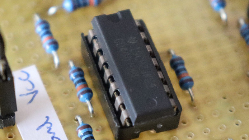
I try to understand the photos. And fail.
If I count the resistors: 12 resistors.
I identify all their colors as brown-blue-black-orange-brown, which is 160k. According to the components list it should be 100k, that is brown-black-black-orange-brown.
Either way. that makes no sense at all. It is R-2R, so I expected to see some red-xxxx (R-2R) or green-xx (1/2R-R).
I would created it from R and use 2-Rs for the 2Rs (doooh), because on a tape they should all have somewhat the same error. But there are not enough of it.
Bottom side?
I’m more confused than usual.
I think it’s brown black back orange (1003) and lastly brown is tolerance, which is a 1% tolerance 100k resistor. He did mention the actual value isn’t critical. Each resistor of the chosen value should as close to each other as possible value wise.
He probably used 2 100k resistors in series as a 2R or two in parallel to get 1/2R. since no exact double or half values are common in the E12 or even E96 series. They do exist but are uncommon and probably not as cheap. 75 ohm is an example, combined with 150 ohm would give you the R-2R ratio.
200K in 1% metal film are readily available. Using them in a R2R DAC today, and in feedback paths in Op Amp circuits on analog synthesizer modules for 2X gain/division.
Hello,
yes there are resistors on the bottom side. I’ll add some more photos, thanks for your interest.
Greetz
I think the more common version of ADC was to use a capacitor-based circuit. First, you’d toggle an output bit to reset the circuit and drain the capacitor. Then you’d start a timer and count until the analog input (going through a resistor) filled the capacitor enough to register as a “1” on the input line. The count corresponded to the analog voltage.
That kind of reminds me of how the analog PC game port worked.
It used an NE558 timer IC, four potentiometers and charged/discharged caps to measure the joystick’s position. Or the state of the paddles, respectively.
The keys/buttons were just dgital switches, afaik.
Anyway, the game port could also be used as a low-res ADC that way.
Applications ranged from a somple digitizer for still images (via photo diode), a simple oscillograph, to measure temperature (NTC, PTC), light intensity (LDR, photo diode).
Back in the late 80s and early 90s, there were countless projects being created around the planet. Especially in GW-BASIC and Quick Basic. STICK () and STRIG (), made it very easy to experiment with game port. I fondly remember these pre C/C++ days. Life was so much more fun then. We also had Turbo Pascal, if needed.
Life is still fun.
We’re just old and grumpy now.
Pickup something new.
Pi pico is fun AF! Especially mixed with 3d printed/laser cut mechanisms.
We used to dream of dual core 133MHz PCs…now they’re $4 single chip embedded parts.
U wot m8? STM32F4-Discovery board (STM32F407VGT6) runs at 168 MHz and there used to be time when they were given out as freebies during trade fairs.
“Life is still fun.
We’re just old and grumpy now.”
How true. 🙂👍
I always must remember myself (and my family/friends) not to end up like the other old grumpy people!
To get back on track, I often do the following:
I ask myself: “What would young me do in this situation ?”
This kind of self-reflection often helps to unwind myself/yourself from grumpyness.
“Pickup something new. ”
Aw, yesn’t. “New”.. Yes in the sense of something yet unfamiliar.
No in the sense of current technology. It’s simply too boring to me.
I would rather thinker with RAW technology.
Like 4000 series CMOS ICs (I started with 74x series TTL).
Less microcontroller, more discretee parts, logic circuits without a ROM.
Yeah, I kind of have a faible for 70s era technology. It was so raw.. So untamed. Rawwwr. 😃
Ok, so maybe I can just run Quick Basic 4.5/VBDOS/PDS 7.1/PowerBASIC in a DOS VM on a high-end PC and use a pass-through feature for V.24 ports and Centronics (VPC 2007 had that feature I recall).
That way, I can interact directly with transistors, diodes, tubes etc. Without considering memory or speed limits of AVRs etc.
What would the young me do in this situation?
Get drunk and screw!
Now it’s an either/or. :-(
Total darkness still helps.
‘I look exactly like Brad Pitt in total, complete and utter darkness.’ is my best line.
I remember implementing ADCs in the past, just to realize the MCU didn’t had enough horsepower to get a decent sample (in my country anything above 1MHz clock was very expensive back in the day).
And so implementing my own buffer circuits, and giving up because there was a project in itself just to sampling an analog signal to my application.
Anyway I learned a lot with that…
” a chair of R… 2R resistors” oc, perhaps a chain…
Does anybody ever just toss a filter capacitor on a digital line and call that a crappy DAC?
“if not the most capable” – IIRC from a massive book of circuits in our university library, this R-2R ladder DAC is monotonic (which means that increasing the numeric value of the digital input always produces a higher analogue output value, i.e. the graph of D/A never reverses at any point). That’s pretty decent in fact, and really makes it quite capable.
I have used a single hex CMOS Schmitt trigger in several projects to convert the quadrature pins and push button state of a rotary encoder into an analog value readable by a single MCU ADC input. For each of the three digital values one Schmitt inverter with a pullup resistor buffers the pin/button state. The output of that inverter feeds an R/C filter for debouncing, with the output leading into another Schmitt input gate. Finally the rail to rail output of the second gate is fed to an R/2R ladder input to be summed with the other pins/button. The result is a 3 bit analog value which can be parsed with an if/else chain to determine the current state of both the pins and the button, already denounced. The MCU just has to read the analog value at a regular interval.
R2R DACs are not dead. You can go past 8 bits, but not too far past, if you get more precise resistors and/or do some hand-matching to get them as close as possible. I like precision resistor networks for this task because they are generally quite closely-matched if you pay a bit for the precision.
I designed an automated test bench that has a bunch of different connectors because it’s testing different products but there are several common ground and VSupply connections spread among them. Their integrity has to be verified during a periodic selftest. Instead of adding another 20-something switching points to the design and the extra time needed to commutate those connections and measure continuity one-by-one, I designed a couple R2R DACs. By applying a voltage at the top node and measuring the voltage of the DAC output, with one measurement we can tell not just whether all the connections are correct, but also which specific, if any, circuits are open.
During the COVID lockdowns I did the same thing with a Bourns 4610x-R2R-103LF and a unity gain opamp to buffer the output. We put the whole thing into an arduino shield to serve as a low frequency function generator so my students could do some of their labs remotely.
I was going to make the remark that $1.15 for a 6-bit DAC is quite expensive. Then went to look up the price of 8-bit DACs, and they turn out to be twice as expensive as this one. ;)
So. Only cheaper I can think of, is using an ATTINY214, costing about 0.61 cents. DAC can do 350.000 smps, CPU can run on internal clock at 20MHz. I expect the ATTINY’s DAC has better linearity
Ok, it’s not so educational as this discrete DAC, and as the propagation delay of a 4007 is about 60ns, it can theoretically do about 16.5Msmps as opposed to 350Ksmps.
So, 47 times the speed for 2 times the price, but at the cost of lower linearity.
:P
Do not worry so much about the accuracy of the ladder resistors. The offset voltages and source resistances of the “digital” bits quickly become more significant.
If you are going to use two chips for a ladder DAC, might as well get 8-bit conversion rather than just 6.
Here’s on oldie using two 4050’s that’s as simple as.
https://archive.org/details/byte-magazine-1977-09/page/n67/mode/2up
I’m looking to build a DAC to output a composite video signal from an 8051 microcontroller. Color preferrably, but greyscale will also work. Just need something that works.