An RGB laser projector opened up on a workbench

Laser Projector Needs Hardware Hack After Software Mod

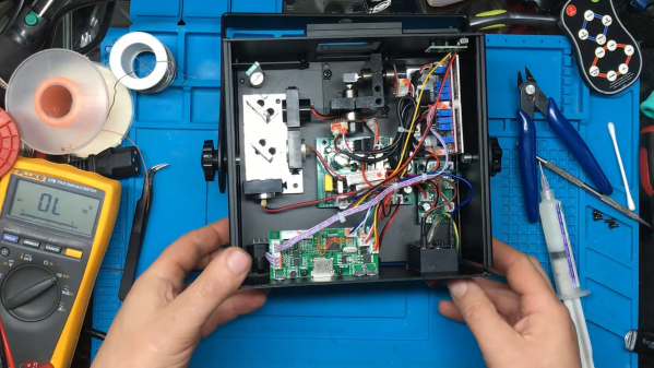
You probably recognize that dreadful feeling when you reboot a gadget after updating its firmware, only to be greeted by a blank screen and an unresponsive device. This apparently happened to the previous owner of a bricked RGB laser projector that [Buy It Fix It] got his hands on: it briefly flashed its laser on power-up but otherwise remained completely dead.

A thorough inspection of the major components didn’t reveal any physical damage, so the issue had to be in software. [Buy It Fix It] managed to connect his Segger J-link programmer to the STM32 main processor and downloaded the contents of its firmware, only to find the remains of a PDF file which seemed to have been accidentally flashed into the chip’s program space. Fixing the device should then just be a matter of restoring the proper firmware, but [Buy It Fix It] wasn’t able to find a copy of it anywhere.

A PCB with a few mod wires on itWhat he did find was Maximus64’s GitHub repository that contained a software mod for a different projector model, as well as its original firmware. Flashing that version didn’t fix [Buy It Fix It]’s projector either, although it did now start to actuate its galvos.

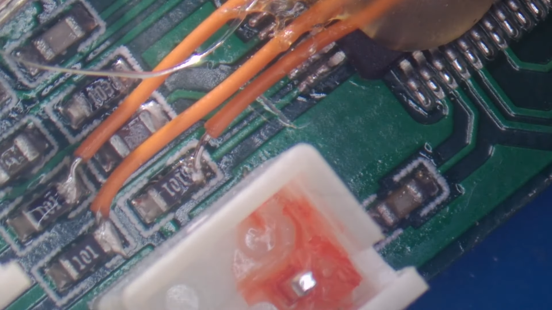
A bit of reverse engineering revealed that the two projectors were very similar from a hardware point of view, but had their laser drivers hooked up to different I/O pins: simply cutting the board traces and soldering some wires to re-route the signals was enough to bring the projector back into a working state.

Having to modify hardware in order to make it fit a piece of software is unfortunate, but sometimes you just have to make do with what you’ve got. If you’ve got no firmware to begin with, then you might even have to write your own from scratch.

Continue reading “Laser Projector Needs Hardware Hack After Software Mod”

See What You’re In For When Buying And Moving A Lathe

Sometimes, with patience and luck, one can score a sweet deal on machinery. But for tools that weigh many hundreds of pounds? Buying it is only the beginning of the story. [Ben Katz] recently got a lathe and shared a peek at what was involved in moving a small (but still roughly 800 pound) Clausing 4901 lathe into its new home and getting it operational.

The lathe had sat unused in a basement, but was ready for a new home.

Moving such a stout piece of equipment cannot simply be done by recruiting a few friends and remembering to lift with the legs. This kind of machinery cannot be moved and handled except with the help of other machines, so [Ben] and friends used an engine hoist with a heavy-duty dolly to get it out of the basement it was in, and into the bed of a pickup truck. Separating the lathe from its base helped, as did the fact that the basement had a ground-level egress door which meant no stairs needed to be involved.

One also has to consider the machine’s ultimate destination, because not all floors or locations can handle nearly a thousand pounds of lathe sitting on them. In [Ben]’s case, that also meant avoiding a section of floor with a maintenance trapdoor when moving the lathe into the house. Scouting and knowing these things ahead of time can be the difference between celebratory pizza and deep dish disaster. Pre-move preparation also includes ensuring everything can physically fit through the necessary doorways ahead of time; a task that, if ignored, will eventually explain itself.

With that all sorted out, [Ben] dives into cleaning things up, doing function checks, and in general getting the lathe up and running. He provides some fantastic photos and details of this process, including shots of the 70s-era documentation and part diagrams.

Watch the first chips fly in the short video embedded below. And should you be looking at getting a lathe of your own? Check out our very own buyer’s guide to lathe options.

Continue reading “See What You’re In For When Buying And Moving A Lathe”

Hackaday Links Column Banner

Hackaday Links: December 11, 2022

“They paved paradise and put up a parking lot.” That might be stretching things a bit, especially when the “paradise” in question is in New Jersey, but there’s a move afoot to redevelop the site of the original “Big Bang Antenna” that has some people pretty upset. Known simply as “The Horn Antenna” since it was built by Bell Labs in 1959 atop a hill in Holmdel, New Jersey, the antenna was originally designed to study long-distance microwave communications. But in 1964, Bell Labs researchers Arno Penzias and Robert Wilson accidentally discovered the microwave remnants of the Big Bang, the cosmic background radiation, using the antenna, earning it a place in scientific history. So far, the only action taken by the township committee has been to authorize a study to look into whether the site should be redeveloped. But the fact that the site is one of the highest points in Monmouth County with sweeping views of Manhattan has some people wondering what’s really on tap for the site. A petition to save the antenna currently has about 3,400 signatures, so you might want to check that out — after all, you don’t know what you’ve got ’til it’s gone.

Continue reading “Hackaday Links: December 11, 2022”

DIY Comparatron Helps Trace Tiny, Complex Objects

Hackers frequently find themselves reverse-engineering or interfacing to existing hardware and devices, and when that interface needs to be a physical one, it really pays to be able to take accurate measurements.

This is easy to do when an object is big enough to fit inside calipers, or at least straight enough to be laid against a ruler. But what does one do when things are complex shapes, or especially small? That’s where [Cameron]’s DIY digital optical comparator comes in, and unlike commercial units it’s entirely within the reach (and budget) of a clever hacker.

The Comparatron is based off a CNC pen plotter, but instead of a pen, it has a USB microscope attached with the help of a 3D-printed fixture. Serving as a background is an LED-illuminated panel, the kind useful for tracing. The physical build instructions are here, but the image should give most mechanically-minded folks a pretty clear idea of how it fits together.

Continue reading “DIY Comparatron Helps Trace Tiny, Complex Objects”

PDP-8 Plays Period Popcorn Piece

[Kyle Owen], collector of antique tech, decided to try his hand at music arrangement — for the PDP-8 computer, that is (listen to the video below the break). He’s using a program submitted by Richard Wilson to the Digital Equipment Corporation Users Society (DECUS) in 1976, appropriately named MUSIC. It runs on OS/8 and is written in the PDP-8 assembly language PAL8. Using the syntax of MUSIC, [Kyle] arranged Gershon Kingsley’s famous Moog synthesizer hit “Popcorn” (the Hot Butter version from 1972).

You might notice the lack of a disk or tape drive in his setup. That’s because [Kyle] is using an RK05 disk emulator he wrote back in 2014. It’s running on a Raspberry Pi and connects over serial, which he says is slower than an RK05 but faster than a tape drive. He has connected up a Cordovox amplifier cabinet for this demonstration, but the original means of listening to the MUSIC output was an AM radio held near the computer (hear the second video below the break). This worked by executing the PDP-8 CAF instruction at a desired frequency, say 440 Hz.

Thus, when this instruction is executed, logic all over the computer goes “zap”, clearing out various registers. Now, if a radio is held close to the computer, it will pick up some of this energy, and at 440 times a second, will deliver a pulse to the speaker. The result is that you will hear a tone from the radio — as a matter of fact, you will hear an A.

Continue reading “PDP-8 Plays Period Popcorn Piece”

A Straightforward Old-Fashioned DAC

With modern microcontrollers, the process of interfacing with the analogue world is easy. Simply enable the on-board DAC or ADC, and talk to the world. If you’ve ever done this with a slightly older microprocessor, you might have encountered the DAC and ADC as chips in their own right, but how about the earliest generation of microprocessors? In those days, if an analogue component was needed, the circuit which would later be integrated on chip would have to be made from scratch. So it is that [Florian Wilhelm Dirnberger] has built a very old-style 6-bit DAC, using a circuit that would have been familiar back in the early 1970s.

At its heart are a pair of 4007 triple CMOS inverters, which form the six bits driving a resistor ladder DAC. This is simply a chair of R… 2R resistors, relying on Ohm’s law for its operation. Each successive bit contributes twice the current to the output of its predecessor, and the 4007 simply provides a buffered supply for the bits.

It’s the simplest of DACs, if not the most capable. Back in the day a typical ADC might also use this circuit, feeding a comparator alongside the input voltage. The microprocessor would count through the digital values until the comparator output bit flipped, at which point it would take the counter value as the analogue measure. You may never need to build one when your microcontroller has one built in, but it’s useful to know how simple DACs and ADCs work.

If the subject interests you, we’ve had a look at DACs including resistor ladders used in audio.

photograph of custom PCB assembly of NE555-based electronic dice

NE555-Based Electronic Dice

It has become a bit of a running joke in the Hackaday community to suggest that a project could or should have been done with a 555 timer. [Tim] has rather taken this to heart with his latest Electronic Dice project, which uses three of the venerable devices.

If three seems like a lot of 555s to make an electronic die, then it may be worth considering that the last time we shared his project he was using 22 of them! Since then, [Tim] has been busy optimising his design, whilst keeping within the constraints of an old-school through-hole soldering kit.

Maybe the most surprising thing about this project is the purpose to which the NE555 devices are pressed. Rather than using them for their famous oscillation properties, they are in actual fact just being used as Schmitt Triggers to clean up the three-phase ring oscillator that is constructed from discrete transistors and passives.

scope trace of the electronic dice ring oscillator
Simulation trace of the three-phase ring oscillator before Scmitt Trigger stages

The ring oscillator cleverly produces three phase-shifted square waves such that a binary combination of the three phases offers six unique states. Six being the perfect number for a dice throw, all that then remains is to figure out which LEDs need to be switched on in which state and wire them up accordingly.

To “roll” the dice, a push-button powers up the oscillator, and stops it again when it is released, displaying the random end-state on the LEDs.

It can be fun to see what can be done using old technology, and educational to try to optimise a design down to the fewest parts possible.

[Tim]’s earlier project is here if you want to see how the design has evolved. The documentation on both of these iterations is excellent and well worth a read.

Continue reading “NE555-Based Electronic Dice”