There are a variety of wheel designs out there that can provide for rotation and translation in various directions. The differential swerve drive, though, as demonstrated by [WildWillyRobots], uses regular wheels on a complex mount to achieve impressive directional flexibility.
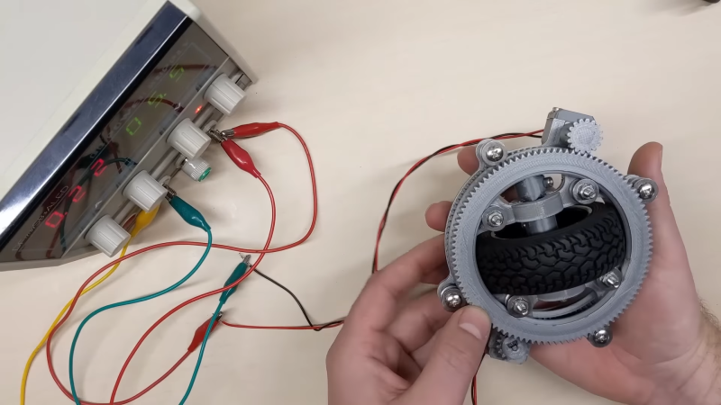
The design uses a regular round wheel mounted on an axle, which has a gear on one end. This allows the wheel to be driven. The wheel and axle is mounted upon a circular carrier, which is then fitted with a pair of surrounding gears on bearings. Differentially driving these gears changes the way the drive behaves. With both gears driven in the same direction, the wheel rotates on its vertical axis to point in different directions. If both gears are driven in opposite direction, the wheel itself is driven. Relatively varying the speed of both gears allows the direction and drive of the wheel to be controlled. The result is a wheel that can rotate to any angle, and then be driven forwards or backwards as well.
Fitting a set of these wheels to a robot creates a highly maneuverable platform. As a bonus, it doesn’t have the drawback of poor grip that is common with various omniwheel-type designs.


Nice idea, reminds me of the wheel arrangement of the Audi in “I Robot” with actor Will Smith, hmm might
be a way to achieve that too with magnetic variations ;-)
Would you perhaps call it a… swervo? *flees*
*yeets FRC catalog at head*
Looks like corexy for wheels instead of 3d printers.
Super interesting but it looks like it may be quite finicky because the motors MUST spin at identical speeds to avoid spinning the wheel and it’s a mechanically complex mechanism. While not nearly as fun, I think just adding a slip ring on the previous design would have far superior reliability.
Reliability aside, if he links all the wheels together then you could run all the wheels with only two motors! The only downside is that while your robot can move directly in any direction, it’s no incapable for rotating.
The identical speeds might be difficult with dc motors, the torque would need to be equal or monitoring the motor speed might be required. Stepper drives might be able to detect a missed step and reduce a step on the opposite motor to maintain wheel direction.
Interesting idea, I could see this device made smaller and a drive shaft going vertically to give the wheel clearance and perhaps attachment similar to the robots earlier in the video. Also see rokon trail breaker
I came to leave a similar comment about the slip ring. The complexity of the design makes using a closed loop control system very difficult. I wouldn’t want to attempt to do any SLAM work on a robot implementing that design of wheel. It is a neat concept if you are fine with just using open loop control.
That type of belt-driven two-motor drive system was popular in the 90s in research robots sold by Nomadic and RWI.
Swerve drive is used in FIRST Robotics by many of the top teams. Our team (8324) is experimenting with one now. Several companies now produce swerve drives for FRC level robots.
The differential swerves have never shown to be worth the trouble in FIRST and seem to be reserved mostly for parlor tricks while the conventional swerves are really rockin’ it.
This past year all the final teams were using swerve drives, my team as well. The are fast, maneuverable and strong.
I beg to differ. I wish I could remember the team number, but about 20 years ago there was a team with a 3 wheel swerve drive that cleaned house all the way to the nationals, as the control system was smart enough to work in the field coordination system. They drive it by just pushing the joy stick in the direction of where they wanted the robot to go, which was just what was needed to collect balls.
That was not a differential swerve drive. Swerve in the traditional sense does and still does clean house due to the maneuverability, but the specific use of a differential results in quite complicated controls problems that even the experienced controls mentor in the program struggle to make work with the restrictions imposed on them by the rules of the electronics.
The first differential swerve module ever even made for FRC that I saw was in 2018, and it was a prototype module made by FRC971 mentors and shown off at the Indiana Robotics Invitational.
What is in your opinion the difference of conventional and differential swerve drives?
Idk, it’s been the hot thing the last few years. Most successful teams have it. Maybe do one research.
That’s brilliant, I’ve thought of this mechanism for driving both axes of an omniwheel, but this turns it inside-out and I think the result is much more rugged since it can use a normal tire.
It looks like this proof-of-concept design can’t bear much weight, since the load on the wheel comes through those sideways bearings engaging a convex edge, and I suspect the author will end up integrating a thrust-bearing-like component at some point. After that, the weak point will be the small gear itself and the difficulty of lubricating and sealing the gears against dust, but that doesn’t look like a design goal here anyway.
Fantastically executed and documented, hats off!
Are you able to supply a link to the CAD files?