
If you’ve been following along our USB-C saga, you know that the CC wire in the USB-C cables is used for communications and polarity detection. However, what’s not as widely known is that there are two protocols used in USB-C for communications – an analog one and a digital one. Today, let’s look at the analog signalling used in USB-C – in part, learn more about the fabled 5.1 kΩ resistors and how they work. We’ll also learn about emarkers and the mysterious entity that is VCONN!
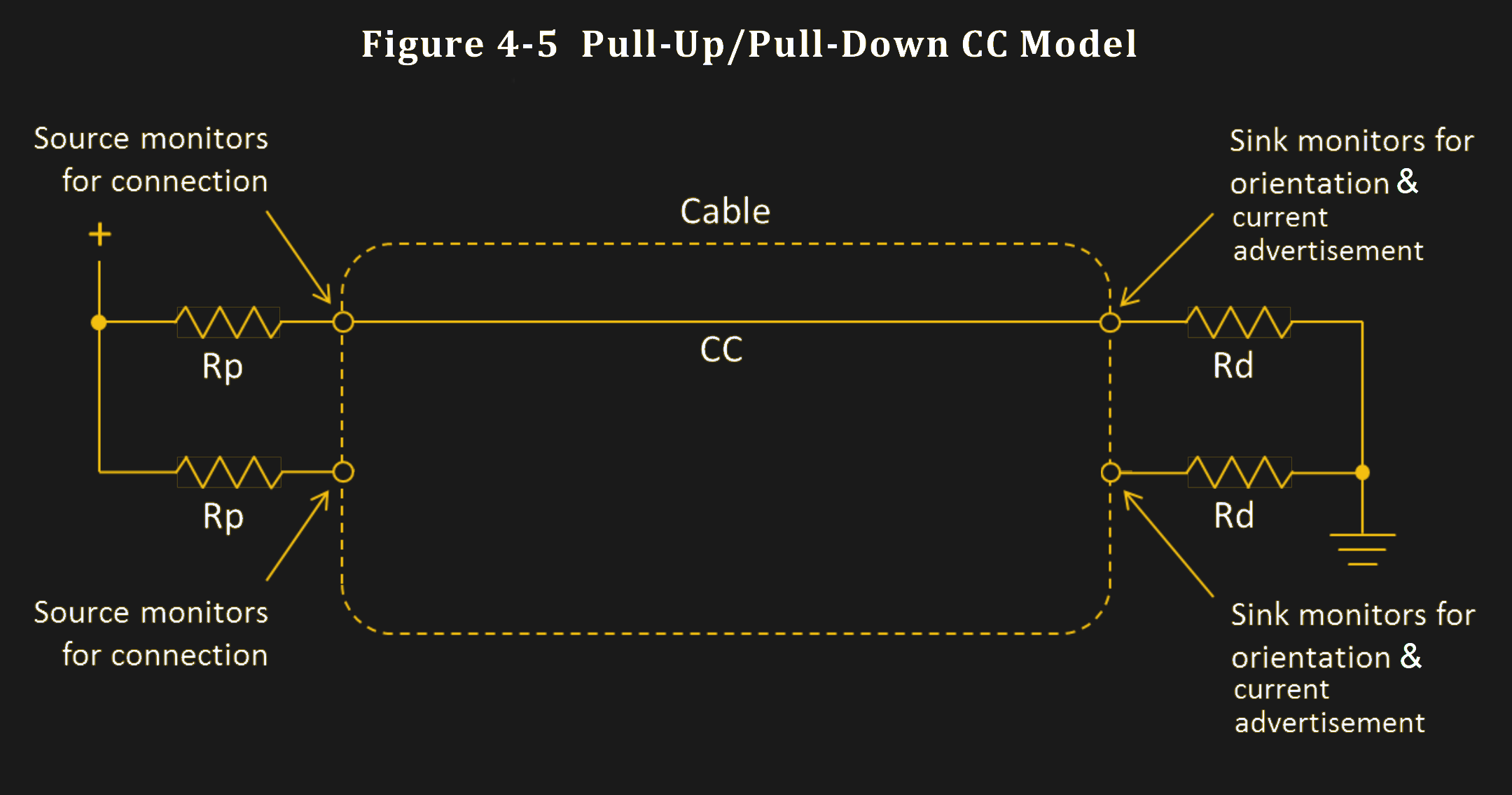
USB-C power supply expects to sense a certain value pulldown on the CC line before it provides 5 V on VBUS, and any higher voltages have to be negotiated digitally. The PSU, be it your laptop’s port or a charger, can detect the pulldown (known as Rd) because it keeps a pullup (known as Rp) on the CC line – it then checks if a voltage divider has formed on CC, and whether the resulting voltage is within acceptable range.
If you plug a device that doesn’t make a pulldown accessible through the CC wire in the cable, your device will never get power from a USB-C port, and would only work with a USB-A to USB-C cable. Even the smarter devices that can talk the digital part of USB-C are expected to have pulldowns, it’s just that those pulldowns are internal to the USB-C communication IC used. A USB-C port that wants to receive power needs to have a pulldown.
This part is well-known by now, but we’ve seen lack-of-resistor failures in cheap devices aplenty, and the colloquial advice is “add 5.1 kΩ resistors”. You might be afraid to think it’s so simple, but you’d be surprised.
Pullups, Pulldowns, And The Resulting Voltage Divider
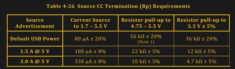
There are two kinds of power roles for USB-C ports – supply side and consumer side. The analog side of USB-C lets designers add a simple way to negotiate power requirements when using USB-C at 5 V, without using specific or expensive ICs – using pullups for sources and pulldowns for sinks. The combination of a pullup and a pulldown forms a voltage divider, and the voltage itself represents the charger’s current capability.
 Now, in analog signaling mode, the source may adjust the pullup based on the power budget available to it, and that’s quite useful. Imagine a laptop or a charger with multiple USB-C ports. As each port gets loaded, there will be less current to give to other ports, which is in large part defined by how the device is built internally. Take the Framework laptop, for instance, which is equipped with four USB-C ports. Each port can provide 15 W at 5 V / 3 A, but if you want to power four sink-only USB-C devices at once, it will only be able to give 1.5 A on third and fourth port – quite a reasonable limitation from an engineering perspective.
This means that higher-consumption devices, like 1.5 A and 3 A max devices, are expected to monitor the voltage on the CC line to determine whether they might exceed the power budget by adjusting their power demands, or otherwise getting shut down if the newly established current limit is exceeded.
What does this mean for you as a user? Nothing, if your devices are low-power enough. Your devices are expected to monitor the voltage on the CC line and adjust their appetite accordingly. Some storebought devices won’t do that, but it’s rare. As a hacker? If you build a device that gets power from a USB-C port and you aim to get full 3 A at 5 V, remember that not all USB-C ports will provide you with that. You can, however, check for 3 A availability by measuring the voltage on the CC line. Or don’t, I’m not your mom, and many a hacker device thrives with zero detection.
What voltages can you expect on the CC line? Well, it’s the kind of voltage you can read with a basic ADC that your microcontroller has, or even a comparator.
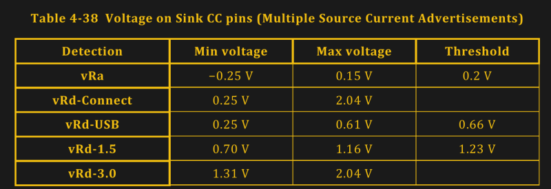
As you can see, it’s all under 3.3 V so you won’t need a voltage divider if you’re using a full-swing microcontroller ADC. Oh, and if a USB-C socket is what you have, remember to monitor both CC pins separately, of course.
Do I Really Have To?
Do you really need to monitor the CC voltage? When you’re just hacking away at something, not really, but it can help if you do when you want to go beyond 0.5 A – 1 A. If you exceed the current demands that the source port can provide, it is supposed to simply stop supplying power to your device – a pretty safe outcome. On the other hand, the USB-C philosophy is to have multiple layers of safeguards, and if you’re building a 15 W device with the simple 5.1 kΩ resistor approach, you might as well make it be a device that can detect its power supply being insufficient. Also, it’s quite easy to do!
Otherwise, you can just expect that your device will want to be paired with a charger that always gives 3 A at 5 V, which the overwhelming majority of chargers out there do. Then, you will never experience problems – always able to work with the full 15 W. If you’re connecting your device to a laptop port, however, be it USB-C or USB-A with a USB-C adapter, you can’t fully expect 3 A to always be there – you actually will want to check.
5.1 kΩ isn’t the only pulldown you will encounter. There’s a different kind of pulldown, which we hackers have met before, and it’s the Ra – something that comes into play when we talk about e-marked cables.
VCONN: Feeding Your Emarker Properly
Emarkers are basically memory chips that can talk USB PD protocol. They’re used in cables that are slightly fancier than normal, i.e. cables with high-speed capabilities like USB3 and Thunderbolt, as well as 5 A cables. They tap into the CC line on the cable, and can be queried by either the source or the sink – though they’re typically queried by the source.
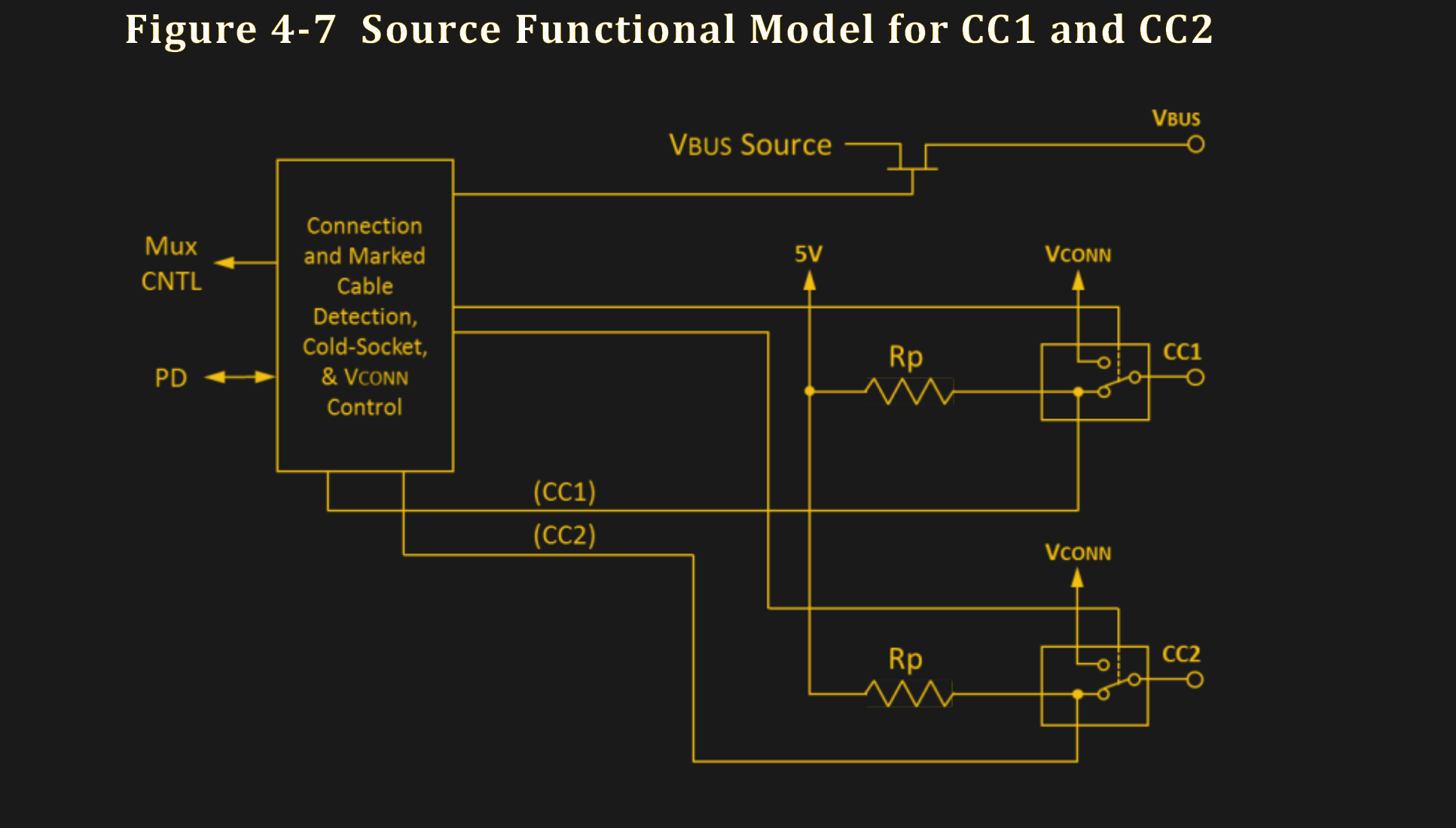
If there’s an emarker inside your USB-C cable, it’s going to need some power, and USB-C has a way to provide power to it – it’s called VCONN. As you know, only one CC pin is used for communication. The opposite CC pin, not connected to a CC line, is used to provide the emarker with power; the other CC pin is VCONN.
Within the USB-C plug, you will know which CC pin is attached to the CC wire, and therefore, you know beforehand which pin will act as VCONN. However, you can insert the plug in two different orientations – and this means that the receptacle has to be able to treat either of two CC pins as either CC communications line or a VCONN pin. This keeps cables relatively dumb and cheap, letting the devices themselves handle the complexity.
As a hacker, you won’t need to worry about VCONN in all likelihood. Most of us will work with USB2 or USB3, no higher than 3 A current, and the emarker check won’t be all that necessary. Going further than that, there are ICs that will take care of a multitude of USB-C aspects for you – including, indeed, supplying VCONN.
The voltage requirements on VCONN are quite lax, as opposed to the 5 V you’re expected to provide to VBUS – the allowed range is 3 V to 5.5 V; often, it’s direct LiIon single-cell battery voltage in smartphone implementations, which means you avoid two conversions and can do quite a bit of power saving. After all, VCONN power isn’t just for emarkers it can be used to power small accessories and headphone adapters with up to 1 W power budget. This fun presentation from a USB-C hacker talks about prototyping VCONN-powered devices that cover the full range of what the USB-C spec allows a VCONN-powered device to do.
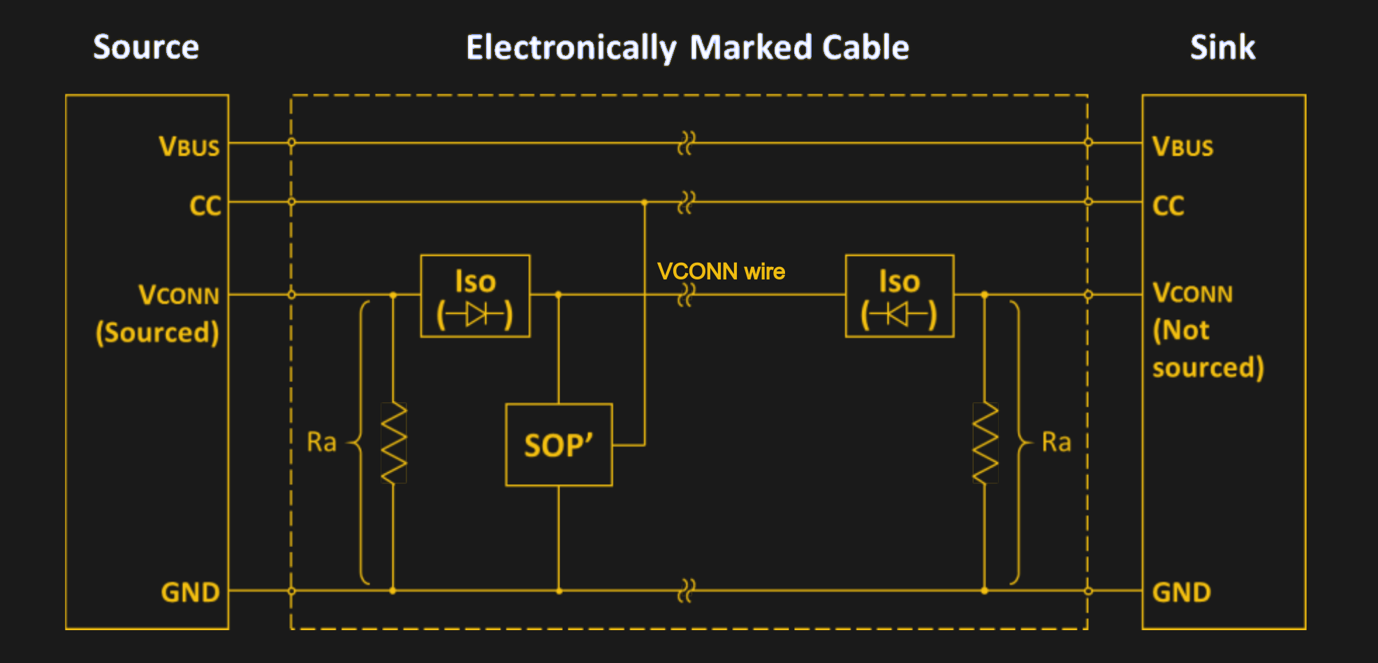
That said, emarkers are the most widespread thing that wants VCONN, and they’re quite simple. Sometimes a cable will contain two emarkers, sometimes it will contain one – it’s a manufacturing choice. In case of a single-emarker cable, one of the cable ends will contain the emarker, and there’s going to be an extra “bring emarker power to other end” VCONN wire run through the cable from the emarker-equipped plug, connected to the VCONN pin on the other cable plug. So, if you ever see a mention of a VCONN wire, that’s what it means – a diode-isolated wire connected to an unused CC pin on one end of the cable, that simply brings power to an emarker on the other end.
Now, this is fun and all, but what about that Ra pulldown thing?
The Ra-spberry Pi 4 Problem
An emarker signals its presence by applying a pulldown resistor (known as Ra) to the VCONN pin; it’s 1 kΩ on average, in the range from 800 Ω to 1200 Ω. If the receptacle is able to provide VCONN, it looks for such resistor on the CC pin not currently used for communications, and feeds VCONN into that pin when the resistor is sensed. This resistor, as a result, is available on the second CC pin inside the cable plug – on both plugs of the cable.
What happens if you short both CC pins together in your device’s receptacle, and then insert an high-capability emarked cable? The 5.1 kΩ resistor gets put in parallel with the 1 kΩ resistor, and you get 840 Ω total pulldown, give or take. This pulldown is what the power supply sees on the CC line, and it’s out of the 5.1 kΩ expectation. Specifically, the voltage divider pulls the voltage too low and the power supply doesn’t provide 5 V on VBUS.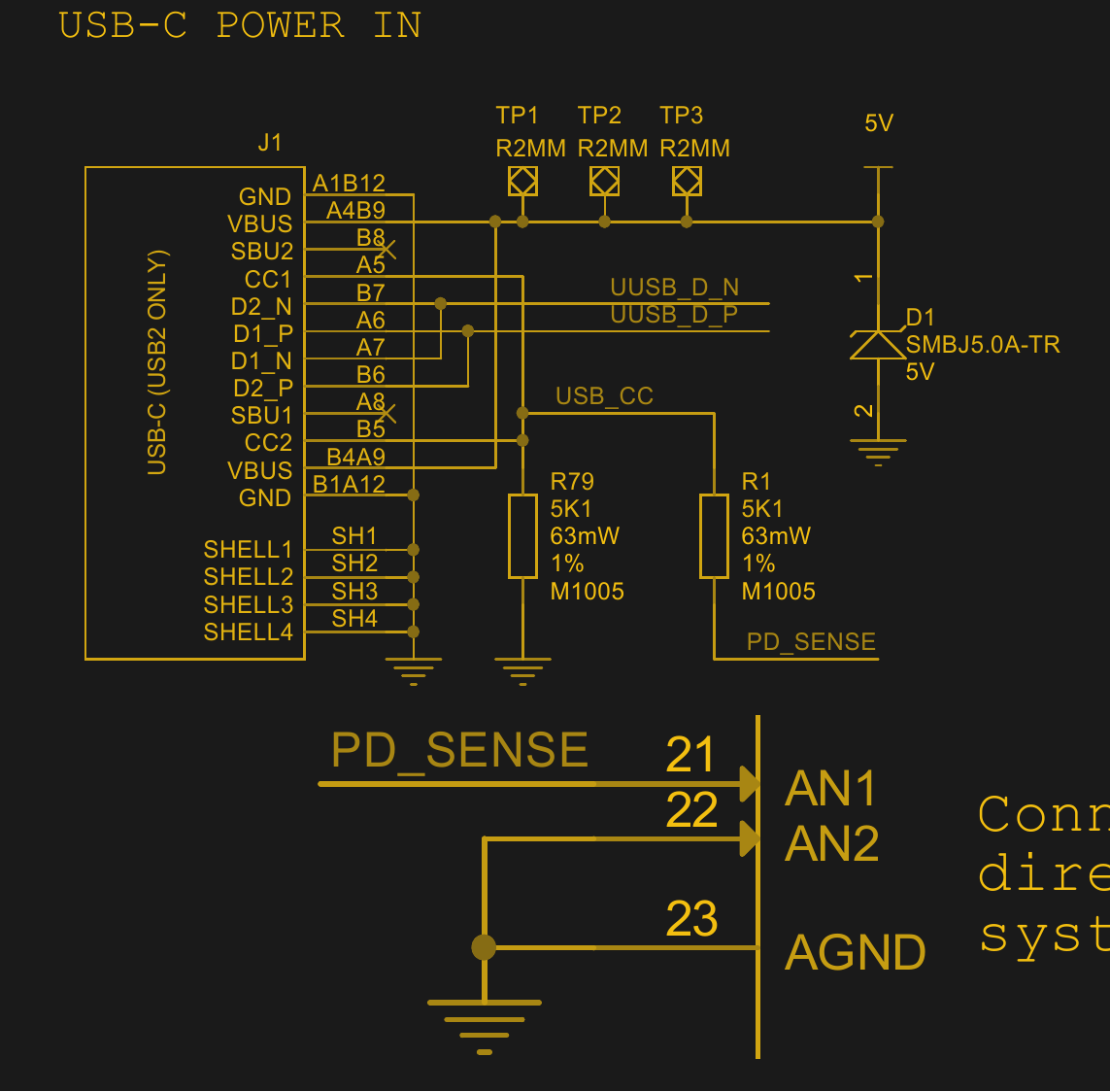
This is what Raspberry Pi 4 did in its first revisions, remember? As a result, you wouldn’t have been able to power the Pi 4 with an emarked cable through a Type-C charger – you’d need a non-emarked cable or perhaps a USB-A to USB-C cable with a USB-A power supply. And, of course, the official Raspberry Pi power supply doesn’t have an emarker in its captive cable. It doesn’t have to have an emarker, either – after all, emarkers are intended for questioning unknown cables, and captive cables are known cables by definition.
The question I’ve seen nobody ask, was – why did they do it? If you check the schematic, you’ll see that the PD_SENSE net from the joined CC pins goes to an analog input pin on the PMIC. You might be able to guess by now – they implemented the “voltage monitoring” part of the standard, but didn’t implement the “emarker” part properly. How much voltage monitoring do they actually do, is questionable, but the capability’s at least there.
Raspberry Pi resolved the issue in upcoming revisions, and if you have an older revision, you can patch it yourself. We don’t yet know how they patched it, but we will eventually find out. In the meantime, this is all what you ought should know about resistors, emarkers and the elusive VCONN.
Next up: USB-C power in ports, power roles, and higher voltages!


“The question I’ve seen nobody ask, was – why did they do it?”
I thought it was stated pretty explicitly at the time that it was a simple case of misunderstanding the standard, not having any emarker cables in their QA process, and not realising that there were cases where emarker cables could fail but dumb ones would not.
Mistakes happen, especially when you’re only just starting to work with a new and complicated standard and don’t have any direct experience of it’s peculiarities yet.
that’s not ‘why did they do specifically what they did’, that’s ‘how was it that a mistake happened’.
>If you exceed the current demands that the source port can provide, it is supposed to simply stop supplying power to your device
What’s the standard behavior though? Does it shut down forever, until the source device is rebooted? Is there any attempt at detecting that the offending device is removed so power can be re-applied? Is the power automatically restored after n seconds?
If the power keeps on getting switched on and off repeatedly, that causes repeated inrush and brown-out conditions on the device and eventually breaks something.
There really isn’t a “standard” behavior for how VBUS Sources manage their overcurrent events and the implementations do vary. In PCs, this varies by BIOS (were the overcurrent event to occur in prior to OS boot) and operating system. Windows as an example, has a sort of “three strikes” rule where if three consecutive overcurrent events are detected within an interval, Windows will disable VBUS power for the particular xHCI/USB hub port until the system is rebooted.
Simpler source ports such as AC/DC USB-C adapters have been found to simply latch-off until AC mains is reconnected. Others use thermal fuse elements as their overcurrent protection which self-reset after cooling off.
A peek into the many different observed VBUS overcurrent implementations in common products would be a meaty standalone article itself.
>Windows as an example, has a sort of “three strikes” rule where if three consecutive overcurrent events are detected within an interval
How do you mean” consecutive”? If I short out a USB cable, does that count as one event until the short is removed?
I mean consecutive in time, not in unique detach/reattach events. In my experience, Windows has not been requiring a physical disconnection of the overcurrent/faulted device before it attempts to re-enable VBUS power & re-enumerate that device. E.g. if you leave the VBUS->GND short present persistently for 10 seconds, you will exhaust your three strikes.
It brings to question whether the over-current protections are meaningful at all. If the system keeps flicking the power on and off, or browns out the voltage to limit current, that can be equally dangerous as not having any over-current protection at all.
From a device developer standpoint, not knowing what to expect means “prepare for everything”, which in practice means “prepare for nothing and hope for the best” because of budget and time constraints, and product designs that don’t allow adequate safety measures like user-replaceable fuses, which would be kinda important when dealing with up to 60 Watts of power without any special negotiations.
What a mess….
The entire point was to move all the complexity of figuring out what-charges-what-and-how for a couple dozen wildly different use cases from the user to the hardware and to do it safely. There’s no avoiding the mess.
Now i’m absolutely convinced that the usb consortium hase been infiltrated by the SSS ( Secret Sadists Society) not giving minimum specs for standards and making a complicated mess of things.
Where do you think all the old-time SCSI developers went?
> Take the Framework laptop, for instance, which is equipped with four USB-C ports. Each port can provide 15 W at 5 V / 3 A, but if you want to power four sink-only USB-C devices at once, it will only be able to give 1.5 A on third and fourth port
3A + 3A + 1.5A + 1.5A = 9A? What’s the source of this limit and why 9A?
It’s got a 55Wh battery that is rated at 3.5 Ah. The mainboard may load the battery at around 1C and 9 Amps is around 2.5C on the battery, so the total system load on the cells could exceed 4C if it were allowed to put out more current. It’s already pretty harsh on the battery, and would likely exceed some thermal design limit.
Don’t forget that 9A is amps, not watts: if it’s all at 5V, it’s 45W, which is a lot of power delivery: thin and light notebooks often have a smaller power adapter. (Often 35W)
Gotcha. Sorry, not that electrically inclined l. :-(
So, the idea is to have a voltage divider on each, CC line with a coefficient of 1 / 3 ( 10K, 5.1K ) in order to supply 5V, 3A. Can other resistors, with the same coefficient be used? There are very many USB C receptacles, but, most of them have internal, built in resistors. I would like to use them with extra resistors in order to make the same voltage on the CC lines. Looks like the receiver measures the voltage on the CC lines, so, this should not be a problem. Of course the values must be such, so, not too much current is drawn. There will be a problem in case the receiver measures resistances, but, not voltages.
There are capacitors on the CC lines of the receiver ( and maybe the charger ). The lower the divider’s resistors, the higher the cutoff frequency. Thus, with lower resistor values, there would be, slightly, more noise, but, not a big deal.
Also, the CC lines are NOT used for communication when 5V, 3A is used ( Rp = 10K, Rd = 5.1K ).
A USB C receptacle or plug has 24 pins. 4 pins are for ground, 4 pins are for VBus. Therefore, there are, only, 24 – 4 – 4 + 2 = 18 logical pins. Most of these are for differential signals ( two are used for one ). However, most manufacturers try to save Copper and make their cables very inexpensive, thus, they do not use all signals. I have been able to measure, only, 10 logical signals ( with an extra board ). In Chinese terms, only, CC1, DP1 and DN1 are used, along with Vcc ( VBus ) and Ground. In all cases, Vcc ( VBus ) is connected to Vcc ( VBus ) and Ground is connected to Ground. On a Samsung Galaxy A03s cable as well as on most cables CC1 is connected to CC1, DP1 to DP1 and DN1 to DN1. However, there are cables, where, CC1 is connected to CC2, DP1 to DP2 and DN1 to DN2. Looks like the receiver needs to measure one of the CC lines, only ( with the other disconnected to give 0V ). However, because of various types of cables, the best is to put an Rp = 10K between CC1 and VBus as well as betwen CC2 and VBus on the charger, so, the two CC wires display the same voltage ( although, acquired separately ).
Also, when only the voltage is measured ( unsure whether this is the case ), the two CC lines can be connected. This would connect the 5.1K resistors in parallel to make 2.55K. Therefore, another 5.1K ( not 10K ) is needed between the connection of the CC lines and VBus. This, however, is only good when the receiver allows such a connection. However, in case the received applies voltage between the CC lines, this voltage will be shorted and either the receiver would burn ( unlikely ) or the short protection will be activated ( likely ).
Anyway, please, comment, clarify or answer the questions!
No. A CC pin CANNOT be used as VCON, because, each CC pin must have an RP of 10K and cannot have Ra. This is because, again, there are differenc cables. Some of them connect CC1 of one of the plugs to CC1 of the orht. Some of them, CC1 to CC2. All of these must be atisfied. Thus, a 5V, 3A cable must NOT have an eMarker nor any electronics nor any resistors. Just, pure Copper from one end to the other.
Hello everyone,
I am currently developing a device with a microcontroller that has a USB2.0 module. USB-C is to be used as the physical connector (so that the device looks modern). I have the problem described above that when using a USB-C cable with an E-marker chip, the resistance on the CC line is not 5.1kOhm, which means that no 5V is applied to VBus. Is there a solution (resistor circuit or similar) with which the problem can be properly solved?
I have found my problem. Unfortunately, both CC lines were terminated together in my application. As soon as I have provided a separate termination for each CC line, the detection works as desired.
Hello everyone,
I am currently developing a device with a microcontroller that has a USB2.0 module. USB-C is to be used as the physical connector (so that the device looks modern). I have the problem described above that when using a USB-C cable with an E-marker chip, the resistance on the CC line is not 5.1kOhm, which means that no 5V is applied to VBus. Is there a solution (resistor circuit or similar) with which the problem can be properly solved?