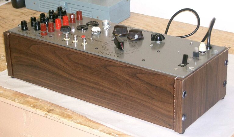
Regardless of the mythical qualities that are all too often attributed to vacuum tubes, they are still components that can be damaged and wear out over time. Much like with transistors and kin, they come with a stack of datasheets, containing various curves detailing their properties and performance. These curves will change as a part ages, and validating these curves can help with debugging a vacuum tube-based circuit. This is where one can either spend an enormous sum on a commercial curve tracer like the Tektronix 570, or build your own, as [Basin Street Design] has done.
A semi-retired electronics design engineer by trade, he has previously covered the development of the curve tracer on Instructables for the version 1 and version 1.1. What this device essentially allows you to do is sweep the connected tube through its input parameter ranges, while observing the resulting curves on an attached (external) oscilloscope. Here a storage oscilloscope (or DSO) is immensely helpful to capture the curves.
In the project pages, the in-depth theory and functioning of the circuitry is explained, along with the schematics and a number of builds. The project has been around since before the VBA tracer which we covered last year, both of which are infinitely more affordable than a genuine Tektronix 570.
Thanks to [Fernando] for the tip.


When I was in school for electronics back in 79/80 tubes were still everywhere and I worked a lot with them, solid state was still gaining ground. I’m fascinated at how much tubes are gaining again. I’ve heard people comment on how audio quality just isn’t the same with solid state and digital. I can’t really tell the difference until an old James Bond movie comes on. Back in the day those Brits really knew how to make a sound system work on the bones. I guess the smooth flow of electrons through tubes instead of the super high efficiency switching of solid state devices is where it’s at. Tubes were not quite as sensitive as transistors and MOSFETs. But then I can for sure say I remember hearing 60hz buzz in tube systems when an electrolytic was going bad and all the RF noise from those point to point wired circuits when shielding was off, missing or not adequately grounded. I also remember getting lit up a few times from some of those old circuits. I’m glad CRT’s are gone now. I never did feel comfortable working around those especially after getting into a TV set the mice had been in, or having to worry about breaking the neck off of one of them trying to get it through a door way.
It is not a singular difference but one of the main components of this pleasant “tube sound” seems to be related to tubes producing even harmonics (x2) while semiconductors generate uneven harmonics (x3). And in modern day, due to people putting a LOT of effort and money into tube amps while 99% of the semiconductor amplifiers you run into are built to be as cheap as possible.
I think the “tube sound” actually has less to do with the tube, and more to do with the topology of the circuit. Since most tube amps use audio output transformers to couple the high output impedance of the tube to the low load impedance of the loud speaker, I’m betting the harmonics are generated due to the current lag as the audio is being coupled through the transformer. I’ll just bet that if you built the circuit using a high voltage MOSFET in the same topology, you’d still get that warm “TUBE” sound?!?!
Actually allot of early commercial solid states amps did exactly this. The coupling through a Transformer acted as a dc protection for the amp if something shorted and for the speaker if the transistors blew up. I’ve been looking for these amps for a minute to listen to but there usually ratted to hell
Remember me when I had to shuffle hundreds of pounds of Hollerith punchcards through the city, and my oxcart was failing me. I´m glad punchcards are gone now. I never did feel comfortable working around those (especially if the tolerance was slightly out of spec) because of trypophobia.
I really can wait until no James Bond movie comes on.
“I’m glad CRT’s are gone now. I never did feel comfortable working around those especially after getting into a TV set the mice had been in, or having to worry about breaking the neck off of one of them trying to get it through a door way.”
I do miss CRTs. Old VGA monitors, TTL monitors..
Monochrome CRTs had both a fine and soft picture, without any pixels (they operated with lines).
Just look at those beautiful green monitors and amber monitors! So pretty, so soothing..
Colour CRTs had a mask, TFT/LCD technology have little square pixels..
Both not very pretty, if you ask me.
Personally, I have no interest in an oscilloscope with a TFT screen.
A scope needs to have a CRT, otherwise it doesn’t look “alive”. But that’s just me.
I was so glad to get rid of my 19 inch color monitor, that barely fit on my desk. So even a smaller monitor was better once I found an LCD monitor on the sidewalk.
I’ll gladly trade the grain of even a monochrome CRT for the pixels of a LCD. Even the beautiful NeXT display was annoying that way. And don’t get me started on RGB shadow mask misregistration, and the response of a Trinitron to vibration, and the susceptibility to magnetic fields, and the desk space they took up. And the heat, and the awful 16 kHz whine (though, I’m at immune to that one now).
I’d be a little concerned about not having the screen voltage switched by the “push to test” button: with no plate voltage, the screen can draw substantial current. Just a thought…