The original Nintendo Game Boy is a stout piece of hardware in a solid plastic enclosure. [Raphael Stäbler] recreated the popular handheld on a breadboard instead, in a fully-functional way, to boot.
[Raphael]’s build doesn’t rely on a real Game Boy CPU or components. Instead it’s emulated with the aid of a Teensy 4.1 microcontroller. [Raphael] coded up an emulator from scratch, instruction by instruction, something he’s documented on his own blog. The Teensy is placed on a breadboard, and hooked up with a series of 8 buttons to serve as the controls. Audio output is via a LM386 acting as a simple audio amp, hooked up with an original Game Boy speaker for more authentic sound. Display is thanks to a FT81x display driver running a small LCD. Games are loaded via an SD card formatted in the FAT32 file system.
While it’s not as ergonomic as the original Nintendo console, it works, and works well! It’s an impressive project to see the Game Boy recreated from scratch inside a powerful microcontroller. We’ve seen other projects go to similar lengths before. Video after the break.
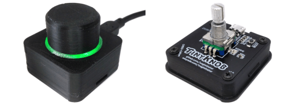
The scroll wheel might be the best thing that happened to the computer mouse since, well, the computer mouse. But sometimes you want something a little more tangible. For example, with a software-defined radio setup, it doesn’t feel right to scroll your mouse to change frequencies. That’s where [Wagiminator]’ USB knob would come in handy. Marrying a 3D printed case, some addressable LEDs, a rotary encoder, and a CH552E microcontroller, the knob appears to the host operating system as a normal USB keyboard. That means most programs can use it without any special drivers or software.
There’s honestly not much to the hardware. A custom PCB holds two WS2812’s, the tiny CPU, the encoder, and the USB plug. There are a few random discrete components, too, but not many. Everything you need is on the project page. The PCB layout, the software, the schematics, and the 3D print files. The code that does the main work is extremely simple. The USB code is a bit more complex (look in the include directory) but honestly, it isn’t as bad as most USB examples we’ve seen.
This project is ripe for hacking. The software is simple enough to modify easily. The 3D printed case wouldn’t be hard to spruce up or print in different colors. Following the example, this would make a reasonable core for a custom keyboard peripheral that used exotic keys instead of a rotary encoder.
Knobs can be simple or complex. If you want our take on the odd volume control, we used sonar.
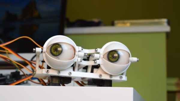
It’s not Halloween yet, but if you’re planning a technically-complicated costume, it might serve you well to start building now. To that end, here’s a guide from [Ikkalebob] on how to produce a compact animatronic eye mechanism.
The eye is inspired by mechanisms used in professional animatronics. However, that doesn’t mean it’s hard to build. Complex machining is done away with in favor of readily reproducible 3D-printed components. The eyes are able to look in different directions and can move realistically, and the build includes working eyelids that have a great blinking action to them that feels very natural. An Arduino Uno is charged with running the eyes, paired with a bunch of hobby servos and an Adafruit PCA9685 servo driver. A hefty 5V, 4 amp power supply is on hand to deliver enough juice so the servos move smoothly without stuttering.
It’s the kind of thing that’s perfect for your spooky familiar, or installing eyes in the back of your head. It would be perfect to hide behind a window or in the bushes, too. Video after the break.
A month ago there was disappointment as Virgin Orbit’s first attempt at a space launch from the United Kingdom using its converted Boeing 747 airliner platform failed to achieve orbit. Now with the benefit of a lot of telemetry analysis the company have released their findings, which conclude that a fuel filter within the second stage became dislodged. The resulting fuel starvation was enough to cause the engine to receive insufficient cooling and overheat, bringing the mission to a premature end.
As we said at the time, the interesting part of the launch, midair from the 747, appears to have gone flawlessly. Space exploration is hard, and we are confident that they’ll fix any fuel filter mounting issues on future launches and be placing payloads in orbit for their customers soon afterwards. The whole program has seen significant news coverage in the UK where the craft has its base, and those of us in that environ will no doubt see it portrayed locally as a matter of national pride. The truth however will be that it flies on the talents of engineers from all corners of the world. We’ll be watching out next time, and look forward to a successful mission.
Header: Österreichisches Weltraum Forum, CC BY-SA 4.0.
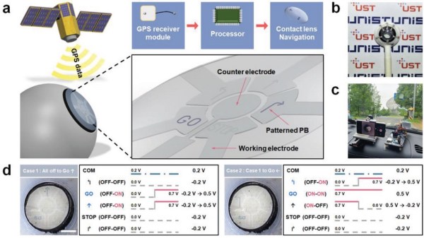
Augmented Reality (AR) promises to relieve us from from the boredom of mundane reality and can also help you navigate unfamiliar environments. Current AR tech leaves something to be desired, but researchers at the Korea Electrotechnology Research Institute have brought AR contact lenses closer to actual reality.
The researchers micro-printed FeFe(CN)6 ink onto the contact substrate and thermally reduced it at 120˚C for nine seconds to form Prussian Blue, an electrochromic pigment. By confining the material with the meniscus of the ink, resolution was better than previous techniques to display data on contact lenses. While the ability to reversibly change from clear to blue faded after 200 cycles, the researchers were targeting a disposable type of smart contact lens, so degradation of the display wasn’t considered a deal breaker.
Since voltages applied were constant, it seems this isn’t a true bi-stable display like e-ink where power is only required to change states. The on condition of a section required 0.5 V while off was -0.2 V. The researchers printed a contact with straight, left, and right arrows as well as STOP and GO commands. Connected to a GPS-equipped Arduino Uno, they used it to navigate between ten different checkpoints as a demonstration. Only a 3D printed eyeball was brave enough (or had IRB approval) to wear the contact lens, so watching the state change through a macro lens attached to a smartphone camera had to do.
Shielding is crucial for all manner of electronic devices. Whether you want to keep power supply noise out of an audio amplifier, or protect ICBMs against an electromagnetic pulse from a nuclear attack, the basic physics behind shielding remains the same. A Faraday cage or shield will do the trick.
At times, though, it would be desirable to shield and unshield a device at will. A new class of materials known as MXenes may be able to offer just that functionality, with microscopically thin films serving as shields that can be switched on and off at will.
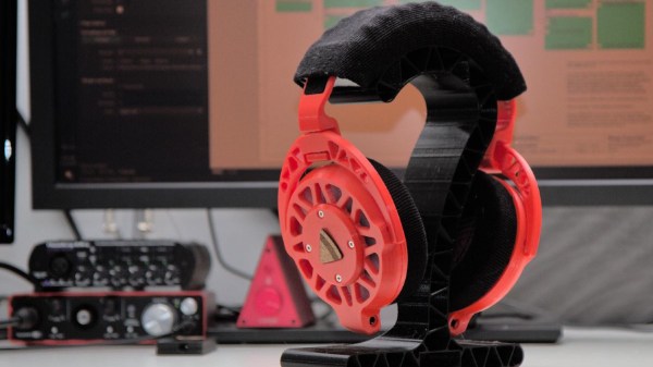
We’ve seen many DIY headphones projects on these fair pages over the years, but not many that are quite as DIY as the Ploopy Headphones. What makes this project interesting is the sheer depth of the construction, with every single part being made from what we might call base materials. Materials such as 3D printer filament, foam and felt, and the usual metallic vitamins.
The electronics are fairly straightforward, with an RP2040 functioning as the USB audio interface and equalizer function. Audio samples are emitted as I2S into a PCM3050 24-bit stereo codec which generates a pair of differential output audio signals. These are then converted from differential to single-ended signals and passed on to the coil drivers. The coil drivers consist of no fewer than eight-paralleled opamps per channel. All of this is powered by the USB-C connection to the host computer. Whilst a kit of parts is available for this, you can make your own if you wish, as the full source (Altium designer needed for tweaks) is available on the Ploopy headphone GitHub.
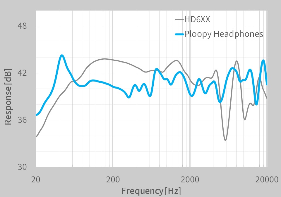
A pretty ploopy response
Many DIY headphone builds would likely be using off-the-shelf speaker units, with large parts of the ear cups being taken from spare parts kits for commercial offerings. But not the Ploopy. The drivers are constructed from flex PCB coils with a standard TRRS jack on each side. Magnets for these coils to react against are held in a 3D-printed frame that is attached to the outer cover. The coils are aligned with a special jig and bonded to the ‘driver foam’ with some 3M VHB tape.
The ear cups are constructed with some 3D printed rings, foam pieces, and simple woven material. The resonator plates push into the inner side of the cup, and the assembly simply screws to the driver assembly. The incredibly detailed assembly wiki makes it look easy, but we reckon there are a few tricky steps in there to trip the unwary. The headband again consists of printed spring sections, some woven material, and foam with a few metallic vitamins thrown in. That makes it sounds simple, but it isn’t.
On the whole the build looks fantastic, but what does it sound like? The Ploopy team has tested them against a pair of Sennheiser HDRXX giving a broadly comparable response, but we’re no audio experts, and the proof, as always, is in the wearing. This project seems to be the ultimate in audio tweakability, with the punchy RP2040 capable of running six audio filters at the full 48 KHz, 16-bit audio, though, the PCM3050 is capable of more.
Want to build some headphones, but need a Bluetooth interface? We got you covered. Can 3D printed headphones ever compare to the big names? We’ll see.