If a hacker guardian angel exists, then we’re sure he or she was definitely AWOL for six long years from [Aaron Eiche]’s life as he worked on perfecting and making his Christmas Countdown clock. [Aaron] started this binary clock project in 2016, and only managed to make it work as expected in 2022 after a string of failures.
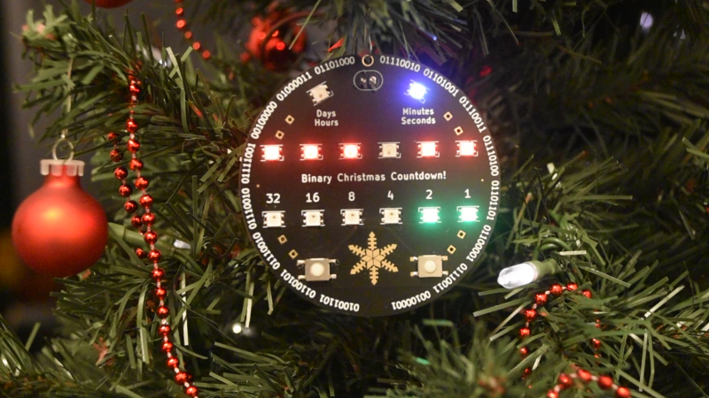
In case you’d like to check out his completed project first, then cut the chase and head over to his Github repository for his final, working version. The hardware is pretty straightforward, and not different from many similar projects that we’ve seen before. A microcontroller drives a set of LED’s to show the time remaining until Christmas Day in binary format. The LEDs show the number of days, hours, minutes and seconds until Christmas and it uses two buttons for adjustments and modes. An RTC section wasn’t included in the first version, but it appeared and disappeared along the six year journey, before finding a spot in the final version.
The value of this project doesn’t lie in the final version, but rather in the lessons other hackers, specially those still in the shallow end of the pool, can learn from [Aaron]’s mistakes. Thankfully, the clock ornament is not very expensive to build, so [Aaron] could persevere in improving it despite his annual facepalm moments.
Lesson 1 : ALWAYS verify circuit functionality and check Schematic / PCB layout before fabrication
The Christmas ornament is not truly a “binary” clock, but rather a binary-coded-decimal clock using six bits instead of the more usual four or eight bits for BCD encoding. [Aaron] would need four banks of six LEDs each to display number of days, hours, minutes and seconds. Adding a pair of buttons for control brought his GPIO count to 26. To make things simpler, he decided to use just two banks of six LEDs each, with an additional pair of LEDs to indicate if the display was showing days and hours or minutes and seconds. This brought down his GPIO count to a more reasonable number. With this feature list, [Aaron] laid out the first version of his PCB, consisting of an ATmega328, the LEDs, a coin battery for backup power, and a pair of capacitive touch buttons. And this is where his problems started. The connections between microcontroller and programming header were wrong. And the capacitive buttons never worked because capacitive pickup signals were never consistent. Beyond this, his memory is a bit fuzzy to tell us if the rest of the circuit actually worked or not.
Lesson 2 : ALWAYS check manufacturer’s data sheets and verify schematic symbols and footprints
For version 2, he ditched capacitive buttons for physical ones, used an I2C based LED driver to reduce GPIO count, and added a RTC chip with battery backup. This version would’ve worked if he hadn’t messed up the connections to the four pin crystal connected to the microcontroller.
Frustrated with his previous attempts, [Aaron] decided to design a proof-of-concept prototype board based on version 2, just to test all of the functionality. But in this attempt too, he failed miserably with several new issues cropping up. He managed to fix a minor track routing issue for the ATmega328 with a bodge wire.
Since the LED driver and the RTC chip both used the I2C bus, the number of GPIO pins required was reduced to a large extent. To test if he could use a smaller controller instead of the ATmega328, he added an option for mounting an ATtiny45 microcontroller. But all of this effort was pretty much laid to waste due to the wrong footprint used for the LED driver which prevented him from getting any useful test results. On hindsight, he might have had a greater chance of success if he had only fixed the incorrect crystal footprint from the previous version.
Lesson 3 : ALWAYS keep notes of your progress
An upgraded version 3 was supposed to have fixed the previous mistakes, but unfortunately, added some new ones during the process of modification. [Aaron] didn’t maintain any notes or records, and in the few years since then, he has forgotten what worked and what didn’t.
Lesson 4 : See Lesson 2
Version 4 was a big upgrade. The discrete LEDs and I2C LED driver were replaced with WS2812 RGB LEDs, and the ATmega was replaced with an ESP8266 module. Also, the RTC section was removed, in anticipation that the ESP8266 could get time over NTP. A buzzer was thrown in to play tinny christmas tunes. But [Aaron] failed once more when he used WS2812 footprints in the design, but soldered SK6812 LEDs which he had lying around. While the two devices are similar, the mapping between their pin numbers and pin functions is rotated by 180 degrees, which essentially resulted in a power supply short and a super hot PCB. An intermediate version 4.5 was attempted, but like version 3, he does not have any written notes or recollection of what went wrong.
Lesson 5 : See all of the above
For the next iteration, [Aaron] replaced the ESP8266 with an ESP32 module but missed adding the auto-reset circuit making it difficult to program the device. Programming was further hampered due to two of the programming pins being shorted during assembly. He also added the RTC section once again, just in case it was not not possible for the ESP32 to obtain time over NTP. Due to the global pandemic and the resultant chip shortage, he had trouble sourcing a voltage regulator in the same footprint that was on the PCB. And in version 5, he once again made the rookie mistake of using the wrong footprint for the RTC chip. To add to his woes, he used some ‘cool’ tiny push buttons, but they turned out to be so tiny as to be practically impossible to use.
Lesson 6 : Persevere, and you will succeed
Having repeated all of his mistakes at least twice over his five previous attempts, [Aaron] finally wizened up enough to take care while designing and assembling his last version. And was rewarded with a fully functioning Christmas Countdown Binary Clock.
Binary clocks seem to be a favourite amongst hackers, maybe because muggles cannot read them, and we regularly end up featuring some amazing projects here on Hackaday. But it would be interesting to know if any of our readers had a project that went through more iterations or took longer than [Aaron]’s monumental project. Let us know in the comments.


No wonder Fail of the Week articles have not been regularly posted!
[Aaron] has been hogging them all!
B^)
I did last week make a project and reused a part from a failed project from 2001, but I was genuinely surprised with the absensce of fail (only a corrupt SD card, me forgetting a configuration file edit and misediting one, and choosing the wrong distro twice: http://iivq.net/home-entertainment-rebuild-1/ )
Looks like a model ornament of Doctor Theopolis.
I too got caught by the LED pinout mess. Both Inolux and HongBright have the corner mark on the package on pin 3, not on pin 1 like every other device has…
I too had the problem of pinout,which is not the same between 5050 and 3535 leds. Fortunately you can rotate the led. The pinout is less than ideal, but you still can have the four pinds touching their pads on the PCB. At least you can mount one PCB and use it to fix the other bugs on it. :)
Lesson 1-6 should be: find the mistake, fix it and carry on. Next rev includes the fix.
But I’d guess that Christmas was over and the project was shelved until next year
Get everything* working, even if it’s horrible mess of cut tracks, dead-bug components and bodge wires. Then incorporate all of these into version 2. On every PCB always put test points for power and signals, and LABEL them on the silkscreen!
Except for that one time I fat-fingered a link on the schematic and tied 5V to GND. That one was too much effort to repair and the PCBs went straight to the e-waste bin.