Radio amateurs often have a love-hate relationship with home-made inductors, sharing all kinds of tips and tricks as to how the most stable nanohenry inductor can be wound. But there’s another group in the world of electronics with an interest in high-quality inductors, namely the audio enthusiasts. They need good quality inductors with a values in the millihenries, to use in loudspeaker crossover networks. [Homemade Audio] takes us through their manufacturing process for these coils, and the result is a watchable video resulting in some very well-made components.
The adjustable former is a machined aluminium affair of which we’re treated to the full manufacture. It’s likely the same results could be achieved with a 3D printed reel. The free-as-in-beer Coil64 on Windows is used to calculate the dimensions and number of turns, and it’s set up on a jig with a cordless screwdriver doing the winding. The best technique for flat layers of turns is explained, and a coat of varnish is put on each completed layer. We’re guessing this is to stop the coil “singing” at audio frequencies.
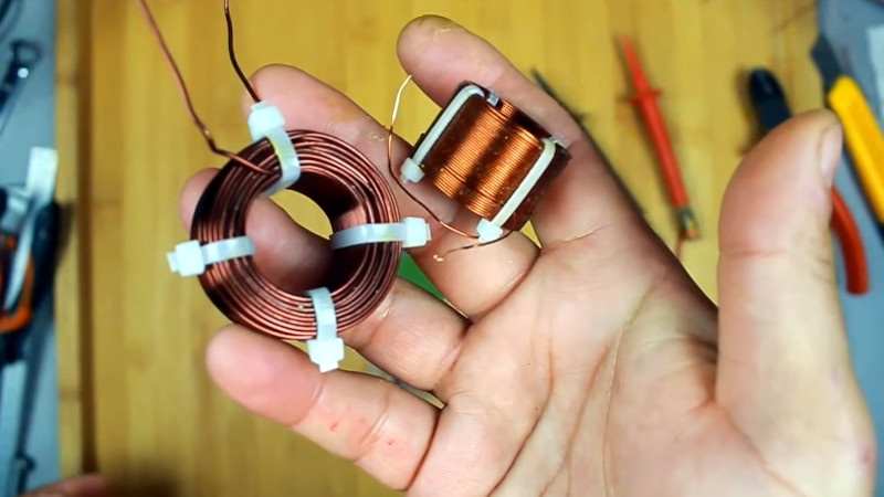
With a set of cable ties holding it together the result is a very tidy component. It’s adjusted a few turns to get the right value with an LCR meter, however experience tells us that a tiny percentage either way won’t harm the resulting network too much. If you make your own speakers, the video below the break could be extremely useful.
Need a loudspeaker primer? We have just the article for you.


I did a deep dive into making coils for one of my projects.
The typical coil formula (the one you find on Wikipedia) only works to audio frequencies, it tops out at about 100 KHz. Above this, a handful of competing issues come into play that are negligible at the lower frequencies, that make your coil a different actual value. Most inductance measuring devices work at 10 KHz or 100 KHz and track the naive formula, so the engineer has no reason to believe the coil is not what he thinks.
Specifically, at higher frequencies the reactance from the inter-winding capacitance becomes non-negligible and subtracts from the rated inductance. The capacitive reactance is larger with higher frequencies and at a high enough frequency the capacitive reactance equals the inductive reactance and you have a self-resonant single component (with no inductance). Overall, the rated inductance will be smaller depending on frequency of use.
Any inductance formula that does not take frequency into consideration will be noticeably wrong at RF.
Furthermore the naive formula says nothing about the Q of a coil, and designing a coil with high Q is complicated.
Further furthermore, very high Q RF coils are apparently impossible: some experimenters with excellent setups have suggested that the maximum Q you can achieve physically is about 1000. (Compare with 50,000 Q variable capacitors that you can purchase). Just about anything – including the presence of conductive material anywhere in the vicinity of the coil – will tamp down on the Q.
A Q of 200 is a reasonable goal, and 800 might be doable in special circumstances.
If you’re interested in designing coils, the full formula for coil parameters is presented on this (not mine) web page:
https://hamwaves.com/inductance/en/index.html
I took the math behind that web site and converted it into a javascript library that does the same calculations, then added some functions to “scan” across coil parameters and print out the values shown on the site. Using a simple program and knowing some fundamental physical parameters you can scan through different coil designs to maximize a parameter for your project.
For example, in my project I need a 25 uH coil wit high Q. I specify a wire diameter and coil value then scan through all possible widths and lengths of coil, the program finds the number of turns needed to achieve the coil value, and prints out the Q (and other information). From this I can choose a configuration that has a calculated high Q value. (Calculated Q values can be as high as 4,000, but see above.)
I could do the same calculation and choose a coil with shortest wire, or the smallest total volume, or whatever the designer needs.
(If there’s any interest in the library or program, IM me on IO and I’ll put it up as a project.)
Wow, that sounds great!
I’d say i have interest, but at least currently no use.. and not much time. But that sounds like something that would be very well used in the community
@PWalsh, I am have only started getting back into electronics (after many years away), and inductance, coils, etc. are the one topic I need as much help with respect to information, how-to, and in your case, calculations. So if you have time, it would be great to see the library/program – along possibly your ‘journey notes’ in getting to where you got. Thank you in advance.
Look for the project “High-Q” in my .IO space in about a week.
Just a friendly reminder!
You run into the same issues with caps. Those generic component testers are good at a lot of things but not really good at anything. I keep one on my bench, but I also have my trusty genrad if I have special circumstances. That has inputs for external excitation.
If you are interested in making coils for RF, K6STI has done an incredible amount of work on the subject and created a free program to design and analyze them. http://ham-radio.com/k6sti/coil.htm
To reduce the parasitic capacitance there is a method called basket winding, which reduces parasitic capacitance and energy loss due to coupling.
Also the best and most detailed formulae for anything related to electronics I found in old books for radioamateurs.
Oh boy am I interested! I going to need an RF filter for PWM output (for a Raspberry Pi), and I would rather make it myself than try to find and purchase one that fits my needs. Interestingly, I think I need a lower Q, because I want the filter to cover two bands, but maybe the best solution would be two filters, a low pass and a high pass, both with higher Q. Whatever the case, I would love to have a calculator to make coil design really easy!
On seeing the phase-plug protrusion 4″ speaker in the video tag I realize this audio only. Hams needn’t read unless you’re into long wave basement frequencies VLF. Even then basket weave winding comes to mind.
Some of the techniques used can be adapted to RF inductors. Obviously not all can though.
Added bonus… zip tie scalpels !
Interesting speaker design on the channel where above video came from “rubanoid”. The speaker membrane is made of two thin plastic sheets rolled in two tubes.
https://youtu.be/F_CDiy84yMw
Great channel and the first of his series on these excellent, but dirt cheap flat panel speakers:
https://www.youtube.com/watch?v=zdkyGDqU7xA
Reading the article title I thought you meant something like this:
https://www.navy-radio.com/commsta/holt/holt-helix-1501.jpg
“The capacitive reactance is larger with higher frequencies.”
That is the opposite of what happens. The reactance of a capacitor is inversely proportional to frequency. Below resonance, the parallel combination of inductor and and distributed capacitance increases the reactance compared to a pure inductor.
Anyone have a good pointer on iron core inductor design? Specifically what style should the core take to maximize power handling? A simple straight block, a loop with or without a gap? I have an E core from the transformer of a small welder (about 10kg of silicon transformer iron), and figure I could re-stack it into the best configuration. Would it be better to make a big straight bar, or a loop with less cross section area.
I need to design for very high currents. It’s the smoothing element for a DC welder. I am not aiming for a specific value, anything will help with compared with the “none” currently employed.
The priority is to avoid the core going into saturation. Peak current could be 250 amps, about 8 kw. (typical currents would be about 100A, 4 kw). The coil will only be about 50 turns, as I am using ~7AWG wire.
I recently took my Extra exam for my U.S. Ham license. One of the question is about iron core inductors. According to the test question, iron powder is used in cores to maximize power handling. Solid iron will have too much hysteresis losses, especially at higher frequencies and higher current, which will lead to your inductor overheating (and at welding current, possibly even melting). A laminated transformer core might work, reconfigured as you mention. Iron powder maximizes isolation and thus minimizes losses (and thus core heating). I don’t actually remember whether iron powder has better or worse saturation than ferrite…Just did some Google, iron powder is better. Ferrite has higher permeability, which allows it to saturate easier, so iron powder has better current handling and avoids saturation better!
So yeah, iron powder. Just make sure your binder is non-conductive and can handle higher temperatures (I honestly don’t know what is normally used here, as I’m mostly drawing on theoretical knowledge rather than practical experience).
We used to entomb the things in blocks of epoxy, so long as there wasn’t going to be a heat problem. We made a paper “mold”, inserted the coil, made sure leads were clear, and when it was done polished off the paper scraps. At last, a physically stable unitary component.