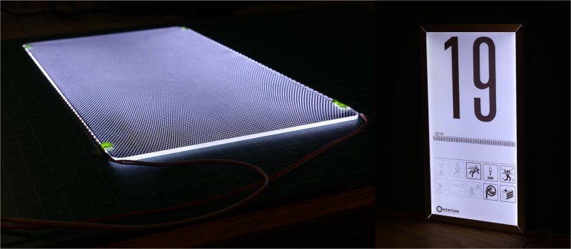
Last year, I found myself compelled to make a scaled-down replica of the iconic test chamber signs from the video game Portal. If you’ve played the game, you’ll remember these signs as the illuminated monoliths that postmarked the start of every test chamber. In hyperstylized video game fashion, they were also extremely thin.

True to the original, my replica would need to be both slimmed down and backlit with a uniform, natural white glow. As fate would have it, the crux of this project was finding a way to do just that: to diffuse light coming in from the edges so that it would emit evenly from the front.
What I thought would be quick project ended up being a dive down the rabbit hole that yielded some satisfying results. Today, I’d like to share my findings and introduce you to light guide plates, one of the key building blocks inside of much of today’s backlit screen technology. I’ll dig into the some of the working principles, introduce you to my homebrew approach, and leave you with some inspirational source code to go forth and build your own.
Hobby and Industry Practices
Tackling this project made me wonder: how do manufacturers in the electronics industry illuminate those ultra-flat laptop displays and TV screens to get a perfectly uniform glow? Following a bit of internet research, I discovered a treasure trove of useful insights.
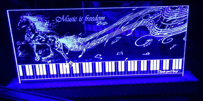
Before we dive too deep into how the consumer electronics industry solves this problem, I want to first walk you through an analogous hacker side-project: the laser-cut acrylic edge-lit display. We’ve featured quite a few projects like these on Hackaday, and they’re just the right level of complexity to get your feet wet at the local Hackerspace.
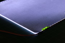
The core concept is that clear acrylic sheets have the ability to act as fiber optics, piping light from one edge to the other. The journey isn’t perfectly straight though. Much of the light enters at an angle, bouncing back and forth between top-and-bottom surfaces before exiting the other edge. By etching a pattern on one surface of the acrylic, we create a location where the light is absorbed and emitted, rather than mostly reflected. We can take advantage of this quirk to create some pretty swanky looking signage.
Something that careful observers might point out: image features that are further away from the light source are noticeably dimmer. To understand that phenomenon, we need a bit of physics.
Some Background Theory: Snell’s Law
Some fairly simple optics theory behind this hacker project can help us understand what’s going on. Let’s start with a cutaway side view of this project where the left side is illuminated by a bar of LEDs.
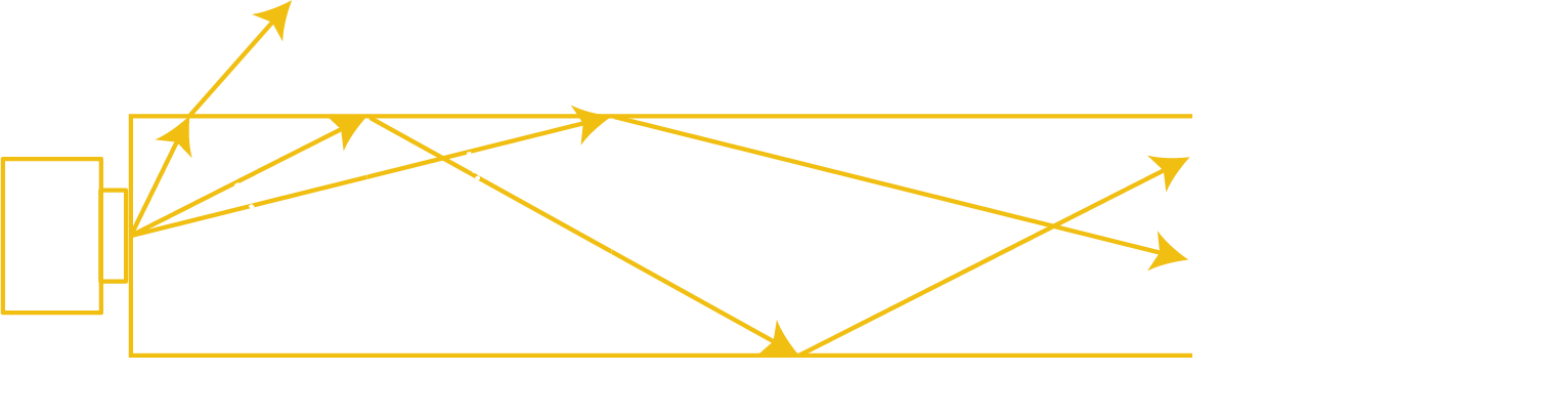
In this setup, a light source shines from one edge of the plate, sending light rays into the plate at a range of angles. It turns out that there exists special angle Φc called the critical angle. Light rays hitting the surface boundary at less than Φc will exit the plate immediately at a slightly different exit angle according to Snell’s law. Light rays hitting the surface at angles greater than or equal to Φc will be totally internally reflected. In other words, they will continue to bounce around inside the plate at a fixed angle forever, unless they are interrupted. For glass and plastic, Φc ≈ 42°.
By etching the surface of the plate, we create locations where the internally reflected light rays can scatter and exit the plate at a specific location, rather than reflect back internally. This is the phenomenon that causes the signs to glow.
At this point you might be able to guess why etched features of the sign become dimmer as they get further from the light source. It’s because a larger portion of the internally reflected light rays have already exited the plate earlier on.
Industry Practices
It turns out that LCD manufacturers implement a backlighting scheme that uses a similar approach to what we’ve seen so far. Peel back the inside of a liquid crystal display to find that it actually consists of a sandwich of many layers. Separate those layers to find a polarizing layer, a liquid crystal layer, a diffuser layer, clear fiber optic sheet, and finally a thin reflective backing layer. This thin fiber optic sheet, called a light guide plate, is illuminated from the screen edge with a bar of LEDs. The goal of this plate is to take internally reflected light from the edge and release it in a controlled fashion along the surface such that the front of the screen is evenly lit.
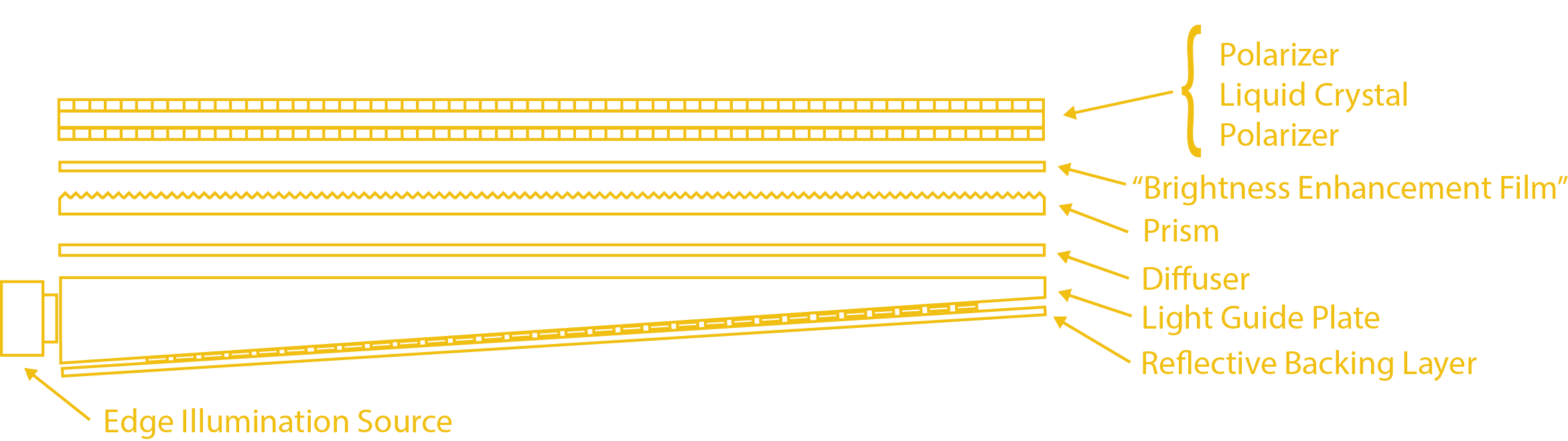
Similar to the sign projects from above, manufacturers mark the surface of the sheet with a pattern of dots, creating escape points for the light to exit along the way. The diffuser layer takes the illuminated light from this pattern and diffuses it further into a uniform light source, and the reflective layer prevents the light from escaping prematurely out the wrong side.
Beyond these basics, though, is where manufacturers start to differ in their own tweaks to this recipe. First off, light guide plates can be made from either acrylic or polycarbonate. They can be either flat or slightly “wedge-shaped,” where the angle of the wedge helps distribute the light more evenly. They can be marked by laser (acrylic only) or by injection mold where the mold actually carries small detents to transfer the pattern. Finally, the dot pattern can vary in density according to a polynomial or exponential function.
From my background reading, I was pleasantly surprised that plenty of vendors will also sell you a host of items relevant to making displays. Reach out to 3M, and you’ll likely hear back with a host of polarizers and “brightness-enhancement” sheets all intended for this purpose. Dig through Aliexpress, and you’ll find vendors offering you a range of “backlight bars” of component LEDs made to replace those found in laptop and tv screens. Dig deeper, and you’ll even find vendors offering made-to-order acrylic panels with a diffuser grid pattern etched onto them, although the pattern options are somewhat limited.
The Homebrew Light Guide Plate Approach
Inspired by my reading, I started with a first-draft making my own sandwich for my Portal sign. While it turns out that you can buy many of the real materials that go into actual LCD panels by 3M, they come at a hefty pricetag in low quantities, so I settled for some cheaper reflective substitutes. My final stack consisted of:
- PET overhead transparency with the Portal sign replica printed on the surface
- 3 mm opaque white cast acrylic, laser-cut to size
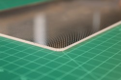
- 3 mm clear cast acrylic, laser-cut to size and etched with a diffuser pattern
- Solar Window Tint Film from Tap Plastics
The stars really aligned well for this project to be something anyone with a CO2 laser cutter nearby can tackle. First, most of the raw materials are either readily available, or cheaper substitutes exist. Second, by nature of these panels being laser cut, the panel edge gets a nice flame polish in the process of being made. This is critical to increase the amount of light entering the panel. Overall, I was thrilled to be doing most of the fabrication in the home workshop.
Quick and Dirty First Drafts
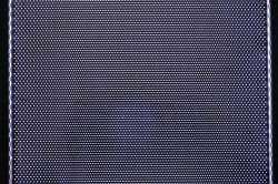
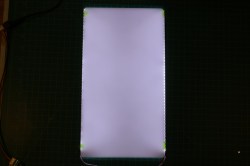
To find out how much effort I’d need to put into makinig an even backlight, I started with something simple. I started by making an evenly-spaced grid etched on the surface of the clear acrylic, covered the bottom with the window tint film, and illuminated it from two sides with two LED backlight bars. As a quick test, I covered the panel with the opaque white sheet and observed it from a distance.
Unfortunately, the results weren’t convincing, but I learned plenty from this setup.
It was clear that the stackup was noticeably dimmer in the middle, the furthest point from the light sources, and the effect was even worse on camera. After another trial, I also noticed that there was an upper limit on how far apart I could space the pattern elements before they started appearing through the diffuser as discrete light sources. I was hoping to avoid writing some custom software to generate the panel pattern, but here we go.
Diffusing Light–Now with BSplines
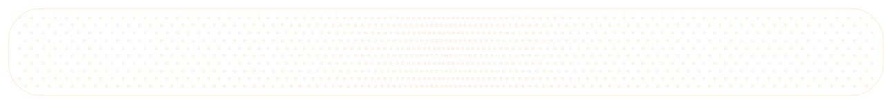
At this point, I realized that I needed some finer control on these laser parameters, so I cooked up a Python notebook to generate a panel of specified XY dimensions with a custom dot pattern and write the result to an SVG file. For tuning knobs, I wanted to be able to manipulate dot density as a function of distance from the light source. To do so, I created an interactive 2D graph where I could drag around 5 points, and fit them to a second order B-Spline. The result looked like so:
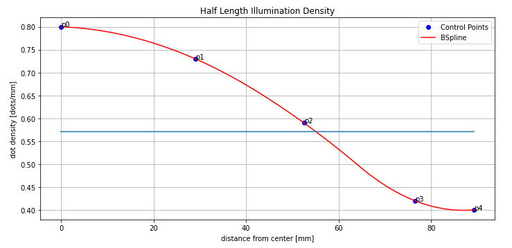
This script I wrote had some nice constraints on it. First, I could enforce a maximum dot spacing so that the script would never generate a pattern that was so sparse that it would appear as discrete light sources. Next, I could mirror the results to apply the pattern to a panel illuminated from two sides. Finally, I could actually record the parameters of my test pieces.
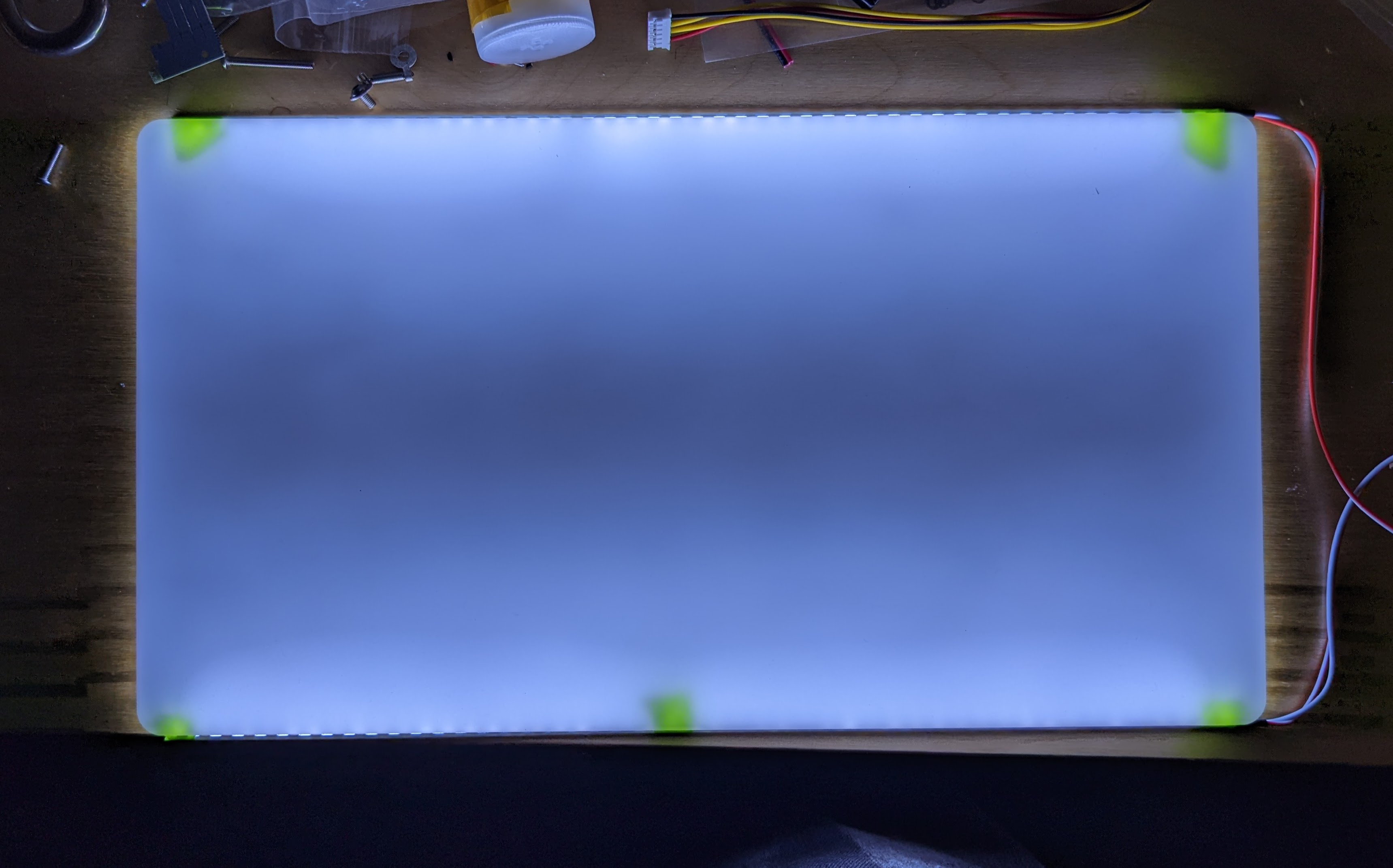
Armed with some new software tooling, I started generating squatty light guide plate samples, illuminating them from both sides under the diffuser, and checking the results. After about 6 tries, I had something good enough to fool me–and my camera!
Feeling comfortable with my settings, I cut a full size piece and assembled my final light plate sandwich.
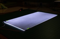
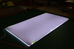
And, without further ado: the final results after assembly.
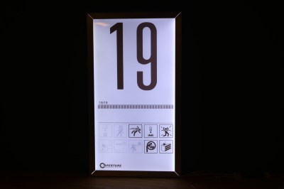
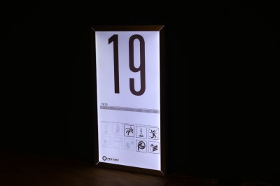
It’s not 100% perfect, but it’s more-than-convincing for both my eyes and for smartphone cameras. It’s also light years ahead of my original naive approach.
As far as software goes, there are plenty of usability improvements worth adding. It would also be a worthy exercise to try to derive the density curve from a calibration image, a flat field correction of sorts. But I’ll leave those items as an exercise for the reader.
We do what we must. because. we can.
This is one of those projects that I was hoping someone had already written up so that I could adopt their results (and credit them, of course!) and use them in my project. In this case, I had to roll up my sleeves and be that someone. But I’m happy to report back with the fruits of my labor. If you’re curious enough to follow this rabbit hole, you are most welcome to have a go at my crude light guide plate generator notebook. Who knows? Maybe in the future, this sort of feature will get integrated into other laser software packages if we ask nicely.
References
- Light Guide Techniques Using LED Lamps. Agilent’s Application Brief I-003.
- optimal dimension of edge-lit light guide plate based on light conduction analysis (Optics Express, Vol 29, Issue 12. 2021)
- Liquid crystal display and organic light-emitting diode display: present status and future perspectives. Light Sci Appl 7, 17168 (2018)
- DF2000MA 8in. x 10in. Reflective Backing layer by 3M, available on Digikey


Why not just harvest the guts of old LCD monitors, instead ?
This. Plenty of dead monitors around.
Custom dimensions.
You can’t just cut the monitor LGP to fit either.
Interesting! Why not? Surely you could at least trim the width?
You can, I did cut a piece out of a 15″ monitor backlight and used it in a portable SEGA made from the lid of a DVD player screen.
Can get a lot of good backlight stuff for free from old PC screens. Also see laptop screens, I probably have over a dozen in sizes from 12.5 (or smaller) to 17″ replaced from the LCD being cracked, backlights are fine.
This can pretty much be made to any size/shape and not limited to whatever lcd you happen to have to strip down. If the end goal is just to get this effect done and the exact size doesn’t matter then just scrapping an old lcd is much easier, but if the goal is to learn how to diy a solution or be able to control specific variables within project constraints then there’s nothing wrong with learning how to make your own light guide.
So you can learn stuff. Too easy for a totally non-utilitarian project. If I had to do this for a specific reason on a timeline, then yeah just cannibalize existing solutions
I grabbed a TV out of the neighbors trash, meaning to take it apart for the lighted panel. After I lugged it home I discovered that it only needed a factory reset to make it fully functional again, and then I couldn’t bear to scrap it.
I gave it to a furniture charity.
I did the same, but couldn’t make it work. Scrapped it only to find two cold joints in the power supply!!!!!
The software RDWorks, which is used to control a lot of DSP-based CO2 laser cutters, has an inbuilt feature which will generate light guide plates. Never used it, but if you happen to have this software, it might be worth a look. There’s a bit in the manual here on page 46:
https://lasermeister.ee/wp-content/uploads/2021/04/RDWorks-V8-manual.pdf
Heck, I completely forgot that I had this software on my pc. Completely swapped over to lightburn… Gonna test the feature this weekend ;)
So I’m wondering if that was the post I wrote on RDWorksLab years ago, and yup, it’s still floating around.
That manual isn’t official, it was written by forum members, including me. Latest should be here: https://rdworkslab.com/viewtopic.php?f=107&t=3507, but members only.
(The mods had a brain spasm early on in the forums life and started deleting users for no real reason, including me. A lot of useful stuff got deleted, ah well, their loss.)
This is why im such a crazy digital packrat. Ive gotten better over the years but Ill keep local copies of all the stuff I feel is really useful and that I could see myself needing or wanting access to later. I feel like things on the internet are definitely becoming less and less permanent as time goes by.
Same but I stash it in archive.org
Thanks for sharing this! I wanted to mention that I started this way, but I cut it because the article was getting really long. My first try with the grid pattern was created using the “LGP” settings in LaserCAD. From there, I struggled to generate anything usable using their built-in density adjustments where the result was either “too dense” in the middle or “too sparse” on the edges. All that said, I think there’s plenty of utility using the built-in LGP generator. It’s fast, and it’s nice that you can overlay the pattern on arbitrary shapes.
If anyone’s curious to see what this looks like:
https://www.youtube.com/watch?v=eRTho3kLq6E
Hey Joshua, I’d love to talk to you about a back lighting application for a large piece of glass art that will be hung in a gallery. I’ve already done the CAD design for the display but I need to generate a dot pattern across and area 27in by 35in such that I get fairly uniform lighting throughout the piece of glass. If you are open to it, would you please reach out to me, iamrickm@gmail.com so I can share my design and discuss the project with you. Thank you!
Something similar in my ceiling. LED edge-light plastic sheet, frosted.
is it edge-lit? Most of those have a lamp at some distance, not the usual backlight setup
Yup, because that’s what needs replacing.
Yep office tile ceiling lights are usually edge lit plastic sheet. I use them as under car lighting when working as if you stand or drop something on the plastic part, no harm done, and the edge is surprisingly robust. And by extending the wiring from the driver to the light its (fairly) low voltage
>why etched features of the sign become dimmer(..) because a larger portion of the internally reflected light rays have already exited
…and got absorbed into the plastic. PMMA has about 92% maximum transmittance in thin sheets, because 4% is lost at entry and exit, plus 0.5% per inch in the bulk of the material with typical extruded plastic. If you have a 13 inch wide panel, the difference in transmittance near and far from the light source is about 6-7%
More precisely 0.96 * 0.96 * 0.995^13 = 0.863
86.3% of the light comes out the far edge vs. 92.2% from the near edge. The difference is largely imperceptible to the human eye, but if you want absolutely perfect light distribution (or a wider panel) you have to correct your dot density and size accordingly.
If you want it to be absolutely perfect, calculate the mean path length through the plastic, not the width of the panel.
Thank you for helping us help you help us all.
What is the solar window tint film for? Just reflecting the light from the “back” of the sign? I did some reading into this some years back and read that apparently an opaque white sheet of acrylic or some other material makes a good backing as it will reflect a lot of the light and diffuse it. I remember reading that a true mirror sheet was not that good as it amplified the appearance some of the uneven illumination (or something like that)
Thine pastry is untrue.
Ditch the solar window film and use something opaque and white, eg thick card, white film, white vinyl, but don’t stick it on! Adhesive is the enemy since it does the same job as the dots and ends up extracting all the light at the edges, negating the dot pattern. Needs to be mechanically fixed in palce.
What are you etching? Is there some black film adhered to the acrylic that you then burned holes (with the laser) which are like tiny windows to the solar window film? It’s a neat trick, but a few more details on that part of the process would help fill in the picture.
In an eerie bit of alignment, it looks like [DIYPerks] could have done with some of this slimmer diffusion techniques for an extra-bright backlight for his dual-LCD panel:
https://www.youtube.com/watch?v=ibEN9FTLdkI
(as it was, he went the super-deep box route)
Thanks for this also. I plan on making somewhat arge (3’x3′ or so) etched, edge lit acrylic signs. I had pkanned on just placing a penny or something under the middle of tge acrylic sheet beinb etched. (So the middle would be etched slightly deeper ythan the edges). So this provides me some good info!
This will be great for making backlight panels that actually illuminate evenly for my HP 3478A multimeters.
Now to find a laser cutter……
Surely you can put your display pattern into the guide as well – ie no dimples where there’s ‘black’ in your design. You’ll probably still need the black mask in the front anyway to maintain edge contrast, but it should help.
This sign is creepy. Seriously.
Anyway, can’t wait for your next post where you describe how you built your first test chamber. Er, 19th test chamber.
In any case, that build was a triumph, a huge success.
I played with this idea a couple years ago when i was trying to slim down some old LCD tv’s.. I realized after my 3rd attempt of making a light guide plate it was cheaper and less effort to buy ceiling office/ grarage/ shop light from the loacal hardware store (like lowes or home depot) and scale down for my project. However, I went down the same exact rabbit hole as in this write up but you explain it much better and with math so this is much appreciated! nice job!
What would the visual effect be of a crack in the lap?
Very nice project and write up!
I got a bit confused on what side you etched the pattern into the akrylic and with how much depth?
The text says initially that you etch it on the top, so the diffuser goes on top of it. But the later images show you have the solar film on top, with the pattern etched into the solar film?
I thought the sandwhich was supposed to be the following from the bottom and up, with up being the side you watch.
—–
reflector/backplate (aka. solar film?)
Light guide panel with LEDs at the edge
Etched pattern in LGP
Spacer
Diffuser (white or opaque acrylic)
Human viewer
—–
Could you please elaborate where you applied the etched pattern and in what order you had the materials layered? :)
Thanks!
/Frederik
Has anyone tried to make the patterns with screen printing?
I pulled down your Jupyter project and had to make adjustments to address some changes in dependencies. I do not have as CO2 laser, but I’ve got a CNC. Turns out this project works great with a 60 degree VCarve bit. My project targets a 8″x10″ plate. See updated code below:
#%matplotlib inline
import matplotlib.pyplot as plt
import drawsvg as draw
import numpy as np
from scipy.optimize import curve_fit
import scipy.interpolate as interpolate
from ipywidgets import interact
from IPython.display import SVG, display, HTML
import base64
Extra fn for rescaling displayed SVGs
_html_template=”
def svg_to_fixed_width_html_image(svg, width=”100%”):
text = _html_template.format(width, base64.b64encode(svg))
return HTML(text)
def svg_to_fixed_width_html_image(svg, width=”50%”):
b64 = base64.b64encode(svg).decode(“utf8″)
text = f”
return HTML(text)
#——————————————————-
#HALF_WIDTH_MM = (178.475)/ 2
HALF_WIDTH_MM = (203.2)/ 2 # 8″ = 203.2mm
#HEIGHT_MM = 327.7375
HEIGHT_MM = 254.0 # 10″ = 254mm
NOMINAL_DOTS_PER_MM = 1.75
DOT_DIAMETER_MM = 0.5
CORNER_RADIUS_MM = 7.5
#——————————————————-
def spline_density_gen(y0, x1, y1, x2, y2, x3, y3, y4):
x = np.array([0, x1, x2, x3, HALF_WIDTH_MM]) # x axis control points
y = np.array([y0, y1, y2, y3, y4]) # y control points.
t, c, k = interpolate.splrep(x, y, s=0, k=2)
spline = interpolate.BSpline(t, c, k, extrapolate=False)
# plot:
plt.figure(figsize=(10, 5))
#plt.axes().set_aspect(100)#(‘equal’)
plt.plot(x, y, ‘bo’, label=’Control Points’) # Plot the control points.
for i,xy in enumerate(zip(x, y)):
plt.annotate(f”p{i}”, xy=xy)
N = 100 # Plot resolution.
xx = np.linspace(x.min(), x.max(), N)
yy = spline(xx)
plt.plot(xx, yy, ‘r’, label=’BSpline’)
plt.plot(xx, [1/NOMINAL_DOTS_PER_MM]*len(xx))
plt.grid()
plt.legend(loc=’best’)
plt.title(“Half Length Illumination Density”)
plt.ylabel(“dot density [dots/mm]”)
plt.xlabel(“distance from center [mm]”)
plt.tight_layout()
#plt.ylim(0,1)
print([y0, x1, y1, x2, y2, x3, y3, y4])
plt.show()
return t,c,k
i_sdf = interact(spline_density_gen,
y0=(0, 1/NOMINAL_DOTS_PER_MM*2, 0.01),
x1=(0, HALF_WIDTH_MM,0.25),
y1=(0, 1/NOMINAL_DOTS_PER_MM*2, 0.01),
x2=(0,HALF_WIDTH_MM,0.25),
y2=(0, 1/NOMINAL_DOTS_PER_MM*2, 0.01),
x3=(0,HALF_WIDTH_MM,0.25),
y3=(0, 1/NOMINAL_DOTS_PER_MM*2, 0.01),
y4=(0, 1/NOMINAL_DOTS_PER_MM*2, 0.01))
Values found after playing around with the interact sliders
y0=0.8
x1=26.25
y1=0.73
x2=56.50
y2=0.57
x3=74.50
y3=0.46
y4=0.40
i_sdf = spline_density_gen(y0,x1,y1,x2,y2,x3,y3,y4)
display(i_sdf)
#——————————————————-
Create the spline function from the density parameters above.
#rho = interpolate.BSpline(i_sdf.result, extrapolate=False)
rho = interpolate.BSpline(i_sdf, extrapolate=False)
def dotspace(x0, xf, endpoint=False):
“””return an array of dot locations from x0 to xf spaced
according to the dot density profile.”””
dots_x = []
x = x0
while x < xf:
dots_x.append(x)
dots_per_mm_x = rho(x)
x += 1/dots_per_mm_x # Step forward mm-per-dot
return np.array(dots_x)
#——————————————————-
Y = np.arange(0, HEIGHT_MM, NOMINAL_DOTS_PER_MM*2)[:-1]
X = dotspace(0, HALF_WIDTH_MM – NOMINAL_DOTS_PER_MM)
xx, yy = np.meshgrid(X, Y)
yoffset = (Y[1] – Y[0])/2.
xoffset = (X[1] – X[0])/2
Y2 = np.arange(yoffset, HEIGHT_MM+yoffset, NOMINAL_DOTS_PER_MM*2)[:-1]
X2 = dotspace(xoffset, HALF_WIDTH_MM – NOMINAL_DOTS_PER_MM)
xx2, yy2 = np.meshgrid(X2,Y2)
Move non-illuminated sides off the top/bottom edge.
miny = min(yy[0][0], yy2[0][0])
maxy = max(yy[-1][-1], yy2[-1][-1])
deltay = HEIGHT_MM – (maxy-miny)
yy += deltay/2
yy2 += deltay/2
TODO: we need to renormalize the output since it has been stretched beyond the width of the original img.
Preview Plot for sanity checking:
fig = plt.figure(figsize=(15,15))
ax = fig.add_subplot(111)
ax.set_aspect(‘equal’)
ax.plot(xx, yy, ls=”None”, marker=”.”, color=”blue”)
ax.plot(xx2, yy2, ls=”None”, marker=”.”, color=”green”)
ax.plot(-xx, yy, ls=”None”, marker=”.”, color=”blue”)
ax.plot(-xx2, yy2, ls=”None”, marker=”.”, color=”green”)
plt.tight_layout()
plt.show()
#——————————————————-
Create an SVG replacing the two meshgrids from above with actual circles.
offset = (10, 10)
fill_color = ‘black’
drawing_width = (2HALF_WIDTH_MM + 2offset[0])
drawing_height = (HEIGHT_MM + 2offset[0])
str_drawing_width = str(drawing_width) + ‘mm’
str_drawing_height = str(drawing_height) + ‘mm’
d = draw.Drawing(drawing_width,
drawing_height,
origin=(-HALF_WIDTH_MM – offset[0], 0),
displayInline=False)
#d.set_pixel_scale(1)
d.set_render_size(str_drawing_width, str_drawing_height)
r = draw.Rectangle(-HALF_WIDTH_MM, 0,
2HALF_WIDTH_MM, HEIGHT_MM,
rx=CORNER_RADIUS_MM,
fill=’#FFFFFF’, stroke=’red’, stroke_width=”0.1″)
d.append(r)
Produce the circle pattern.
Skip duplicate circles to avoid weird bug where LaserCAD software skips etching anything
if there are copies at the same location.
#for xx, yy, fill_color in [[xx, yy, ‘red’], [xx2, yy2, ‘black’], [-xx[:,1:], yy[:,1:], ‘green’], [-xx2, yy2, ‘black’]]:
for xx, yy in [[xx, yy], [xx2, yy2], [-xx[:,1:], yy[:,1:]], [-xx2, yy2]]:
for x,y in zip(xx.flatten(), yy.flatten()):
c = draw.Circle(x, y, r=DOT_DIAMETER_MM/2.,
stroke_width=’0.1′, stroke=fill_color,
fill_opacity=1.0)#, id=’circle’)
d.append(c)
d.save_svg(‘example.svg’)
#——————————————————-
#display(SVG(url=’https://upload.wikimedia.org/wikipedia/commons/f/f6/People_%28example%29.svg’))
svg_to_fixed_width_html_image(SVG(‘example.svg’).data.encode(‘ascii’), width=”100%”)
Super clear LGP explanation. Thanks!
It took me a while to get the code working in the jupyter.org in the web version. The original code used drawSvg which is now drawsvg. You will need “%pip install ipywidgets drawsvg” in the first cell to get those loaded into the web environment. Fortuneatly, my son showed me how to use Gemini to debug the errors. I used Marks code in the comments and the original code to put together to get a working version. I immediately broke it when I switched it to a 3.5″ x 2″ display size. HALF_WIDTH_MM has to be >= 74.5 = x3 which is a requirement of the spine function. I ended up pulling a 1/4 of example.svg to make the pattern progress halfway over the 3.5″ x 2″ to test. I had to convert the example.svg into a 300 DPI bitmap in CorelDraw to avoid it crashing when I went to print the pattern.