If you’ve worked with circuit simulation, you may have run into IBIS models. The acronym is input/output buffer information, and while you can do a lot without having to deal with IBIS, knowing about it can help you have a successful simulation.
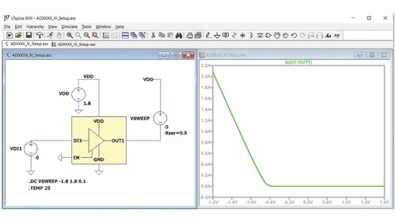
IBIS is an industry-standard format that uses ASCII text to describe voltage versus current and voltage versus time about some device’s digital input and output pins. This allows precise simulation without revealing the device’s internals, which is important to some vendors. The first post of this two-part series talks about what IBIS is and how it got started. The second part explains creating and using LTSpice to create your own IBIS models. It also covers why you might want to do that.
Of course, if you don’t care about revealing the internals of a device, you could just create a Spice simulation. However, many tools will accept both models, so it is useful to know how to produce either kind of model. In fact, to create an IBIS model, you’ll want to use a Spice model to generate the data for the IBIS model, so it is a good bet you’ll have both, even if you choose to only publish the IBIS models.
If you need a refresher on Spice, we have a series. If you prefer using something different, try Micro-Cap 12, which was commercial, but went free a few years ago.


In my experience Input/output Buffer Information Specification (IBIS) [1] modeling is more for verifying signal integrity at the physical interfaces (e.g. Pins) of a device under test. Unlike with Simulation Program with Integrated Circuit Emphasis (SPICE) [2], in IBIS there is no attempt to simulate the overall functionality of the device.
IBIS models are often supported in high-end EDA software suites used for high-speed PCB design. Programmable logic devices such as FPGAs can have complex physical interfaces that can present more than one type of interface to the user depending how they are programmed. Characterizing such interfaces is difficult without sophisticated test equipment (insert sound of cash register bell) such as the four quadrant source-measure-unit (SMU) at lower speeds, the vector-network-analyzer (VNAs) and high-speed oscilloscope at high speeds.
To highlight the difference between SPICE and IBIS this series of articles [3][4][5] from Analog Devices (who now owns Linear Technology Corporation) is interesting:
1. Input/output Buffer Information Specification (IBIS)
https://en.wikipedia.org/wiki/Input/output_Buffer_Information_Specification
2. Simulation Program with Integrated Circuit Emphasis (SPICE)
https://en.wikipedia.org/wiki/SPICE
3. IBIS Modeling—Part 1: Why IBIS Modeling Is Critical to the Success of Your Design
https://www.analog.com/en/analog-dialogue/articles/ibis-modeling-part-1-why-ibis-modeling-is-critical-to-the-success-of-your-design.html
4. IBIS Modeling—Part 2: Why and How to Create Your Own IBIS Model
https://www.analog.com/en/analog-dialogue/articles/ibis-modeling-part-2-why-and-how-to-create-your-own-ibis-model.html
5. IBIS Modeling—Part 3: How to Achieve a Quality Level 3 IBIS Model Through Bench Measurement
https://www.analog.com/en/analog-dialogue/articles/ibis-modeling-part-3-how-to-achieve-a-quality-level-3-ibis-model-through-bench-measurement.html
For folks that prefer to use PSpice, including the free to use PSpice for TI, check out this article on [How to Use IBIS Models in PSpice] (https://emisleuth.com/Articles/How_to_Use_IBIS_Models_in_PSpice_5-15-2024.pdf)