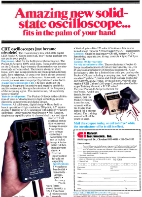
 In the 1980s, an oscilloscope was typically a bulky affair with a large CRT, and a heavy power supply. So it probably grabbed a lot of attention in 1983 when Calvert Instruments Incorporated ran an ad in magazines like Radio Electronics. The ad touted a 5 MHz scope that was pocket-sized and weighed 4 ounces. The ad proudly proclaimed: CRT oscilloscopes just became obsolete!
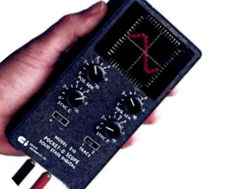
Indeed they would, but if you are wondering who Calvert Instruments was, so are we. We have never heard of them before or since, and we don’t know for certain if any of these devices were ever actually produced. What did it use instead of a CRT? The CI Model 210 Pocket-O-Scope was not only solid state but used an LED screen 1.5 inches square. That’s small, but it packed in 210 LEDs for “high resolution.” We assume that was also the genesis of the model number. Judging from the product picture, there were 14 LEDs in the X direction and 15 in the Y direction. High resolution, for sure!
There were some early LCD scopes (like the Iskrascope and one from Scopex) around the same time, but it would be the 1990s before we would see LCD oscilloscopes and even longer before CRTs were totally squeezed out.
Choices and What about Tektronix?
The ad made two offers. For $180 you could get the unit with “standard probes” that look like they belong with a multimeter. For $250 you could add the carrying case, an AC adapter, high voltage probes that still looked like multimeter probes, and a 200-page training manual.

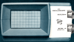
For perspective, $180 in 1983 is worth about $540 today, and $250 would have set back the intrepid hobbyist the equivalent of $750 in today’s money. Moreover, a Tektronix 211 — a comparable CRT scope from the mid-1970s — was a 500 kHz portable scope with 10 NiCads weighed in at a little over 3 pounds. It cost $545 (in 1972 dollars), but you did get a larger analog screen.
While it is true that the 211 was a bit older than the CI 210, later, there were more expensive and more capable 200-series models that had dual channels and higher bandwidths. But not none of them would ever be able to get to four ounces! Phillips and Measuring Instruments also had similar entries.
Other Contemporary Choices
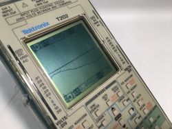
 The Tektronix T202, was a very similar idea to the model 210, but didn’t appear until 1989. It had two channels, a 5 MHz bandwidth, and a 128×128 monochrome LCD. It was a rebranded unit made by another company.
A more common item was the NLS miniscope which was similar to the Tektronix 211, but much less expensive. They were available at least by 1977 and also weighed under 4 pounds, including batteries and the CRT. A 15 MHz unit cost around $300 if you include a probe. You can see a slightly newer model of the NLS in the video below.
What Do You Think?
While many of the scopes mentioned have something in common with the Calvert Instrument scope, there is one difference: we know all of these were actually made. The ads for the Calvert appeared, as far as we can tell, in October of 1983 and vanished after the February 1984 issue. They only appeared in Radio Electronics and we never found any other mention of the company. Was it vaporware? Or was the world just not ready for a 210-pixel LED scope? There were a few later construction projects of similar design, like this one on page 33 of this old Popular Electronics from 1997. For that matter, we’ve seen some contemporary builds with LEDs. But most of the modern toy scopes we see use some sort of LCD. You can only wonder what someone who bought a Tektronix 211 back in the day would think of our Owon HDS272S?
Maybe a Hackaday reader knows the story behind these. If you’ve ever seen a real one or know anything about the mysterious Calvert Instruments, do leave a comment.
Some photos in this post came to us via the excellent TekWiki. Others are from World Radio History scans.


To be honest, it reminded me one idea I had some time ago – if it was possible to create “fake scope CRT” screen with luminophore covered Petri dish and MCU controlled UV-LED matrix. Proper luminophore with coating with afterglow might provide “retro look” but you could use more flexible electronics for the display…
In the early 80s I met a consultant who wore one of those portable Tek scopes (presumably the 211 above) ON HIS BELT. I was a lowly teenager assembling electronics — I barely knew how to program and definitely couldn’t design any hardware back then.
I thought it was cool back then, and looking back I still think it was cool. Honesly teen age me was a bit intimidated by him.
The Sinclair SC110A was a 10MHz CRT mains/battery scope the size of a paperback book, introduced in 1980. There was also a digitiser you could add on.
Today I have two; tomorrow I will have one. Plus a Tek485 :)
https://www.radiomuseum.org/r/thurlby_oscilloscope_sc110a.html
Snap! I have a Thandar SC110A although it’s sadly dead having been left in a damp shed for years and I’ve not had the motivation to fix it as yet.
I would love to get my hands on that SC110A! I love restoring them.
William, Western Australia
HI ChayD,
I would like to make a hit to get it restore, if you may send this to my uncle’s USA address. I appreciated if this is possible! Plz reply when free to my email javed8051@hotmailcom. Thanks
1980’s mail-order. Lots of vaporware then.
Having a merchant account (for accepting credit cards) was a difficult thing to get at the time because fraud was so easy. E.g., you could just take out an ad for a non-existent product and ask folks to mail you their credit card number along with signature.
Reminds me of those early pocket TVs.
They had miniature CRT-like screens.
Here’s an example site I’ve found: https://electricthrift.com/2013/05/27/sony-watchman-fd-10a-and-watchman-fd-30a/
TV change made those obsolete although some had an input jack for other purposes.
As I remember those had real CRT tubes just with and mirror so the screen could be rotated 90 degrees.
Well, no mirror. The screen part is actually the phosphor coated plate and you view though the side of the flat tube.
Here a bare tube without the deflection coils:
https://www.experimental-engineering.co.uk/wp-content/uploads/2016/08/2016-08-16_22-07-26_000293-1-1024×768.jpg
Ah yeah,
you are right. I remember looking on these – had the opportunity to see these BW screens in an old disassembled video intercom.
My first oscilloscope was the Leader LCD-100, and I still have it with me. Just swapped out the battery cells a few years back.
It is a “digital” scope, but what it really was is just a couple oscillators that would run the LCD screen by column and row, and a comparator to decide whether the voltage was below or above the set level, which would trigger the display to show a pixel. All analog behind the scenes. It even makes a different whistling sound depending on the scan rate.
I wondered why there was no mention of the Leader O-scope in the article.
So it was a better version of something like this?
https://hackaday.com/2022/03/29/cute-oscilloscope-uses-leds-for-display/
A company called VuData made a pretty nice portable, single trace 5MHz scope. It would run on internal NiCads or mains power. It used a CRT that was about 1.5″ x 3″ with blue phosphor. The model number was PS910. I bought one used in 1978 and used it through a lot of my college years, working on audio systems and maintaining arcade game rooms. It covered a lot of mileage in my backpack since I used a motorcycle year ’round in those days.
In amateur radio, such LED tuning monitors were used for RTTY.:
There used to be crude devices with an red LED cross that were a cheap alternative to using a real CRT oscilloscope to draw a Lissajous figure for Mark/Space (RTTY banana, RTTY cross). Sorry for the bad description.
See Heathkit HD-3006
“but if you are wondering who Calvert Instruments was, so are we. We have never heard of them before or since, ”
Maybe there was too much Lord Calvert in the Boardroom?
B^)
Forest Mims had a simple LED scope in huis 1982 edition of his Engineers Notebook. It was based on the then common bargraph chip (you could set it to dot mode).
And I think FM had a prior version that used a stack of resistors and comparators for the vertical. I think it was published in Popular Electronics. I’m really stretching my brain cells here…
He published that design many times in many places. The earliest I have seen was in a 1979 issue of Popular Electronics. There he referred to it as a design is regular readers would already be familiar with so… older than that.
At first I thought this was just a bigger version of that same design but there is no way it would go up to 5MHz!
I have the Leader 20MHz analog green scope, cost was 550$ in 1985 era. Still works. Arduino Duo could replace for $200 at 1MHz today.
Based on Google Maps and Street View, there’s still an old brick building at that address. And the company existed from 1983 to 1987:
https://opencorporates.com/companies/us_oh/616335
Not much else to be found on the internets.
Hay, It’s nice to see that someone else knows what a 211 is. I worked at Tektronix starting in 1968 and was the electronic engineer that developed the 211 and 212, and managed the group that built the rest of the 200 series scopes. Needles to say, Tektronix also had the other people to develop the analog ICs, a new CRT, the plastic enclosure and all that. I still have one of each of the 200 scries scopes that I keep charged and use now and then. Tek was a great company to work for. I retired after 25 years at Tek. Dave
Thanks for sharing your story. David! We really appreciate your work! I did not have the opportunity to own a 211, but if I can see one on sale, definitely I’ll get it!
Ah, the LED oscilloscope, good memories. I recall something like that being published as a project on a local electronics magazine in the early 80s: basically it was made of a couple 4017 counters in series, so 20 columns in total, each one enabling the output of a UAA170 (or 180?) which drove the corresponding column, then a few other parts for clock and sync. I’m not surprised it never became a thing: although it had some good teaching value about analog and digital electronics, it was however too costly for a toy and couldn’t be used for anything serious.
The Popular Electronics 20×20 LED ‘scope, linked above, was one of my first real projects…
Unfortunately, the schematic had a bug daisychaining the 401
7s, and I never did get more than 20×1
0 working. I think I recall a followup article fixed it, but req
Uired at least a couple more 400-series chips. I wasn’t sma
Rt enough to figure out a solution before the update, and I guess had lost interest by the time it came out many months later :/
Lesson-learned: 401
7s are cool, as long as you’re only wanting 1
0 outputs. Recently, though, it occurre
D to me
W
E could’ve used 391
4s for horizontal, as well, which would’ve been a bit more like a classic scope anyhow.
[Stupid old phone doesn’t even show a full line of this comment box]
A friend gave me a very old Velleman / Maplins mono LCD scope years ago, it was a decent form factor for toolbox work but the UI was VERY slow.
These days $20 gets you a better kit from China.
In the late ’70s I built a crude LED scope using the LM3914. I seem to recall it had a 10×10 LED screen, with plans to upgrade it with two LM3914 and different chips for the horizontal to get 20×30 LEDs. I had worked out how to make the LM3914/5/6 smoothly change from one LED to the next, so behind a sheet of paper as a diffuser, it looked like an analog change in vertical.
Sadly, I moved out to go to tech school and left a bunch of stuff behind. My parents tossed nearly all my electronics stuff in the trash, on advice of my uncle. My uncle though he was hot snot on a plate, because he worked for a company fixing huge computers. But all he did was replace boards, and he’d find out which was bad by disabling the overcurrent protection, and replace whichever board blew flames out of the tantalum capacitors.
What about the Waterman Pocket Scope?
https://hackaday.com/2017/02/15/taking-apart-a-vintage-oscilloscope/
I just finished restoring two and have another model to do some day.
I’ve got one. Model 210HS. It powers up but one column in the matrix doesn’t light and i’m hesitant to dig into it. I’d love to see it go to someone who would appreciate it. I’m de-cluttering my home in case i die, don’t want to leave a mess and don’t want treasures going in the trash.
I think i might have the manual too.
https://photos.app.goo.gl/NzohFiCevgbaeYH3A