It is hard to imagine experimenting with electronics without the ubiquitous solderless breadboard. We are sure you have a few within arm’s reach. The little plastic wonders make it easy to throw together a circuit, try it, and then tear it down again. But, surprisingly, breadboards of that type haven’t always been around, and — for a while — they were also an expensive item. Maybe that’s what motivated [R. G. Cooper] to build Slip-n-Clip — his system for quickly building circuits that he published in a 1974 edition of the magazine Elementary Electronics.
The system isn’t really what you would think of as a breadboard today, but it was effective and certainly cheap to build. The biggest problem? It wasn’t something you’d use with DIP ICs. But in the early 1970s, you might not be building very much with ICs, and the ones you used might be in oddball transistor-like packages. Things were strange in the 70s!
A Brief History of Breadboards
In the very old days, people built radios and such on wooden substrates that were actually bread-cutting boards. That’s where the name came from. It was common to draw a diagram with the physical layout you had in mind, glue it to the board, and use it as a guide for building and troubleshooting. Wood was easy to drill and cut. A nail or a thumbtack would make dandy terminals. Probably the last time we saw that done was about a dozen years ago in Make Magazine. Even then, it was only a novelty — few people still build circuits like this, but you can see how [Colin] did it in the video below.
If you had students building circuits, this could be a real drag. So, unsurprisingly, [Orville Thompson] from DeVry Technical Institute got a patent in 1960 for a spring-loaded solderless breadboard. Innovative, but not quite how we know them today.
Not Quite There
[Thompson’s] breadboard was more like a spring-loaded patch panel. This would be useful for things you might build on a real breadboard, but in a decade or two, ICs in DIP packages would become a big thing.
In 1971, [Ronald Portugal], working for E&L Instruments, figured out that there would be a market for a board with spring contacts that could accept DIP chips. The patent shows something you’d easily recognize today. AP Products claimed they’d been making solderless breadboards since 1968, but we imagine they looked a lot different.
Of course, breadboards weren’t a common fixture in hobby labs in 1971. By 1977, though, they were small breadboards in the Radio Shack catalog for $9.95 — about half the cost of lava lamp and worth about $50 in today’s money. In 1976, a 6×7 inch breadboard from AP was about $50.
Back in 1974
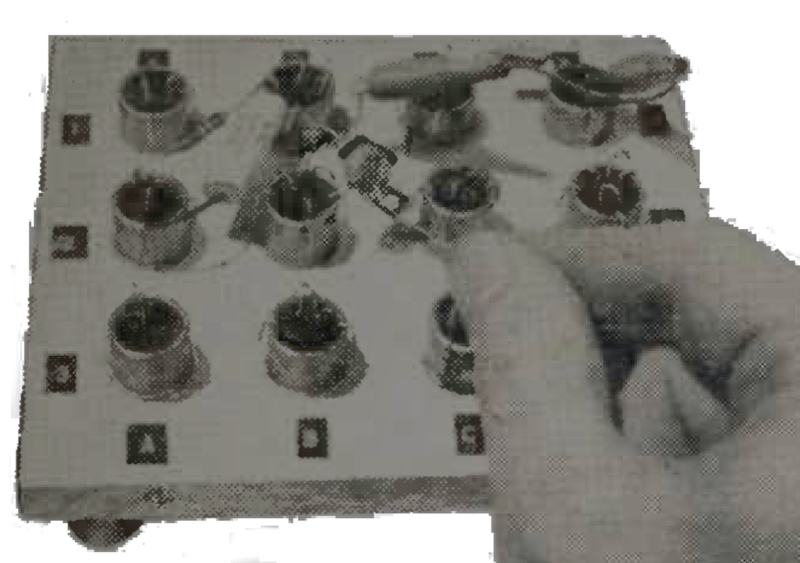
Meanwhile, back in 1974, [Cooper] wanted to put together circuits easily. His solution? A wooden board, some copper pipe, rubber bands, and paper clips. The plan was simple. Drill holes in a piece of plywood to form a grid. The holes were just big enough to pass one-inch pieces of copper pipe through them. Epoxy would hold the pipes in permanently.
That leaves the springs. A piece of scrap wood and some nails make a jig for bending paper clips into hooks that grab the lip of the copper pipe. They also grab rubber bands, so there are two hooks in two different pipes attached to each rubber band. When you pull up on one hook, the other hook pulls back against you. Slip your wire or component under the hook, and the rubber band tension will hold it in place.
Some simple labels finish up the board. Not a bad project, and for some circuits, it may be even better than a conventional solderless breadboard. Of course, not DIP IC friendly at all.
We can see how this would have been an economical solution. You probably had scrap wood, paper clips, and rubber bands hanging around. Copper pipe is common enough, too. By contrast, a 1976 Heathkit catalog touted the new Heathkit ET-3300 breadboard. Four breadboards were mounted in a case with a triple-fixed (+5, +12, and -12) power supply. While $80 doesn’t sound like that much, that was a third of the median US weekly salary in 1976. You also saw a lot of breadboards in cases with things like LEDs, switches, and other external components, but they were not cheap, either. You can see [Lee Adamson] repairing an ET-3300 in the video below.
So we can see what might motivate you to find a piece of scrap wood and stick some pipes in it. Are we suggesting you do the same? Probably not. Although for the right project, it would give a decidedly nostalgic and interesting look. With a little decoration, it would probably look good for a steampunk build, for example.
E&L Instruments literally invented the modern breadboard, but you don’t really think of their name as synonymous with the product. Maybe because they cost $1,300 back then. You can see [CuriousMarc] tear down one he calls an “eBay Disaster” in the video below.
No Fame
The Slip-n-Clip was never very famous, we imagine. But it was a great example of how ingenious people were when they couldn’t just order cheap stuff from the comfort of their couch. We wonder if anyone reading this actually built one back in the day. Let us know in the comments.
Everyone “knows” that solderless breadboard have a lot of extra capacitance and other bad circuit parameters. But how bad is it, really? We’ve seen them subject to all kinds of surgery and even downright torture.


Having lived through that era and experiencing the rise of the breadboard, there a few other options that we had that worked well for us ‘way back then’. The first was to borrow from tube equipment we were all very familiar with prior to transistor circuits. Tube radios dating back before 1930s used point to point wiring. Strips of Bakelite with varying number of lugs were widely available. You’d tack these down to a board and wire your transistors etc directly to the lugs. I made many circuits that way and still do today for simple stuff.
In the late 70s, I attended a conference that touted the benefits of wire wrap which I tend to agree with for breadboard type circuits. With a gun or tool you could quickly wire up something almost as fast as breadboards but with more reliable connections. For changes, just unwrap and rewrap as needed. This handles ics and all manner of components and even with odd spacings – something hard to do with breadboards. It had the added advantage of helping you visualize where traces needed to go when laying out a board manually as we did back then.
It’s fun to read a younger generation’s take on electronics in the 70s-80s. We thought things were really great compared to what we had before. I now marvel at what the WW2 generation did with their electronic designs.
I probably broke some fundamental wire wrapping rules by doing it, but when I got my experimental things working in wire wrap, temporary could be made (more) permanent by soldering. A definite advantage over breadboarding for a hack like me.
I have a wire wrapped and soldered Z80 system from the early ’90’s somewhere that I should try to fire up just for the heck of it.
It would be interesting to see if that Z80 still works and if it doesn’t, is it a wiring problem or a component problem. I’d guess the wiring is good and perhaps a memory chip could be bad as was the case with my 1978 Pet computer. According to Wikipedia, wire wrap connections are very reliable due to the 4 redundant post contacts per wrap. Also,“ The silver-plated wire coating cold-welds to the gold. If corrosion occurs, it occurs on the outside of the wire, not on the gas-tight contact where oxygen cannot penetrate to form oxides.“ so when you get a wire wrap circuit going you’ve got something useable while with breadboards you don’t and you will have to remake the circuit with a more permanent solution.
Plenty of potential failure points could have been attack surfaces over the ensuing 32 years. School project, so wasn’t really built to survive a moon shot or anything.
(It was actually in operation for a year or more after it was built, so 32 years might be a slight exaggeration.)
All of the mechanicals that it controlled are gone to save space, but I don’t think any were required for it to start up.
On failure, my first troubleshooting step would be to reseat all of the chips in their sockets.
Code is in an EPROM. Window is uncovered, but it’s not been exposed to a lot of UV.
It’s inside of an old VCR enclosure, using the original VCR power supply if I remember correctly. Caps could be mostly dead.
2K RAM chip would certainly be a suspect.
2 line x 40 character LCD may have gone ka-put.
For the record, the wire wrapped Z80 built in the early 1990’s and shelved for most of the time since then, fired up without incident. Still accepted keypad input and displayed output on the 40×2 LCD, driven by the original VCR power supply. I guess they made electrolytic caps better back then.
(wire wrapped and subsequently soldered)
I would definitely read an article about this … or a blog post/ if you’ve written one ?
I used wire wrap and perfboard for prototyping and personal projects into the early 2000s. I suppose having a large supply of wire wrap sockets and big reels of 4 different colors of wrap wire that I bought from the surplus store run by my employer had something to do with how long I kept up with it.
When signal rates got into the tens of MHz, noise started to be a bigger problem, and I stopped using it very often.
I find it very convenient to link together the cheap breakout and processor boards from ebay. I use a small hand tool which can strip, wrap and unwrap. Typically I’ll fit all breakout boards with header pins, attach them to some perfboard, wrap everything I can and solder to a few discrete components.
Breadboard, male header pins, soldering it then is what I use with breadboards.
never lived the breadboard like this, what was somewhat similar were nailboard to build wireharness through
The slip-n-clip may not be very famous as “slip-n-clip”, but e.g. the electro experiments boxes from KOSMOS, e.g. the XN1000, 2000,.. and the even older X-series (X1000..) used pretty much exactly this mechanism – just turned upside down and with holes to plug the legs of the parts in.
HaD covered a similar concept to this in https://hackaday.com/2018/08/08/memories-of-a-mis-spent-youth-learnabout-simple-electronics/ which is what got me hooked on electronics back then.
I think those were screws with large cup-shaped heads into a wooden board. Good idea, too, though.
As fabled in the lady bird books – how to make a crystal radio!
Fahnestock clips, anyone?
My dad used those on several transistor radios i inherited.
In my small town, I wonder if any of the hardware stores would have had any.
From the text, I didn’t quite get how that that slip-n-clip system might have worked. So I searched for the magazine; for those wondering like me, it is in March-April issue of 1974, page 81+, available here: https://worldradiohistory.com/Elementary_Electronics_Master_Page.htm
(btw, bonanza of great old texts!)
I had a breadboard from the days before DIP chips – it was called S-DEC and had only about 10×12 holes. It was good enough for small discrete circuits but not very reliable. I didn’t like it much.
I think there may have been higher density versions called T-DEC and mu-DEC.
It’s always interesting to read about obscure American history and how underdeveloped, yet cute certain things were vs the rest of the world. It’s like watching slides of a toddler growing up. 😁
Here in Germany, for example, electronic construction kits allowed for solder-free assembly of circuits since about the 1930s (Radiomann kit, has used wooden/plastic boards with metal springs).
PS: Before veroboards were im common use, there used to be soldering bars (soldering strips). They could be used for smaller circuits and were an alternative to soldering on the flat surface of pushpins/thumbtacks. Soldering strips were also used in ancient tube radios, too.
Radio Shack sold a boatload of kits based on this over the decades. Some of the latest ones included an IC or two wired to the springs in the back.
These are the Radio Shack kits I remember as a teenager: https://hackaday.com/wp-content/uploads/2018/12/pbox_featured1.png
In the late 70’s, we had some RCA trainers in high school, that was a field of banana jack, with four tied together. you could build circuits with plug in resistors and capacitors, but of course the component selection was limited.
Philips made a couple of Philips Electronics Engineer kits for youngsters, which used small springs to attach components to a hardboard base, which had a pot, tuning cap, speaker and switch on it along with a battery holdet. My parents bought me one for doing well in my 11+ exams when I was 11 years old in 1967. I found a youtube vid showing the principle (try 4 minutes into https://youtu.be/Wv7pRovfff0?si=1SjMF3kZZKf2Hg5H )
I moved on to that kit after the Ladybird system. I now work for a successor to Philips Electronics !
Me too. Also had such a Philips kit in he late 60’s. Started me on a career as an EE. Now retired, but still remember he moment I actually understood what a bipolar transistor did.
I remember using the old spring loaded battery clips, you vould get a couple component leads in the clip. Always had a bad connection somewhere, but worked in general
Wonder if anyone still sells the Radio Shack pogo-stick connectors? Sigh…
i had a big mutli-tap transformer i used for powering all sorts of thing temporarily; 20+ terminals with some little proprietary spark plug type shape to them.
I found some big spring stock i could cut and soldered half inch sections to the terminals. made lashup connections so much easier. Just like radio shack “100-in1” kinda kits but with 1/4 inch spring.
I remember building a plywood/nails/copper wire board identical to the one in the youtube snapshot above, when I joined my high school’s lunchtime electronics club.
We did it as a cheaper way to play with circuits designed for the S-Dec mentioned by [adrian] above.
Later, I got something very similar to a “Mykit System 7” for Xmas, as seen at https://andypageelectronics.wordpress.com/2016/12/10/vintage-electronics-kits/
Yes the Radio Shack spring clips pushed into that red square plastic base. Who says you can’t have fun with stone knives and bear skins!
But the really interesting question is:
What battery was used for experimenting?
Say, 4,5v battery (R12) or 9v battery (PP3 shape)?
Here in ol’ Germany, up until ~2000, the 4,5v battery was traditionally being used in flashlights (car flashlights, train signal lamps etc), in electronic construction kits and in school in technology lessons etc.
While in the US, the 9v battery was more common, judging by the articles in electronic magazines?
Anyway, it would be interesting to hear (read) about how it was around the globe. What was the common battery model used for electronic projects? :)
Not sure I have ever seen an R12 battery in the US — I’m sure they’re used for something, but they’re not common.
The 9V/PP3 was very common for smaller electronic projects — but I also saw a fair number of 6V “lantern” batteries in my science classrooms of the ’80s. I think that is largely the US equivalent of the R12; it was used in very bulky flashlights (hence the name). Wikipedia tells me it is a 4R25X in IEC notation, though I don’t think I’ve ever seen it called that.
I wonder how much of that was driven by easy connectivity — all three types can be hooked up with alligator clips without a dedicated battery holder.
Thank you for your reply! 🙂
The 6v lantern battery was also known over here. My father has/had a few in storage, because they make very good batteries for tube/valve projects. The heating often is rated 6,3v..
The main problem with all those “sophisticated Laboratory” do-it-all bread boards is that they always mounted the transformers on the back side of the bread board. That proximity caused the whole system to be incredibly noisy!
(Also they tried to mitigate the problem by using small, barely adequate transformers.)
I bought one secondhand from a neighbor who had attended an engineering school (and was furnished one of these “digital labs” along with a 286-based computer), and after trying to use it once, I disconnected the transformers and replaced them (in the circuit) with higher output ones, except I physically located them more than 12″ away from the rest of the logic circuits and breadboard.
That solved my problems, and I got lots of use out of that thing!