The recent crop of laser cutters are nothing short of miraculous. For a few hundred dollars you can get a machine that can easily engrave and — subject to materials — cut well, too. [Nate] has been taking advantage of a laser to make boxes that join together using finger joinery. The problem is, the pieces have to fit exactly to get a good box. While setting dimensions in software is fine, you need to account for how much material the laser removes — something traditional woodworkers and machinists know as kerf.
You can, of course, employ trial and error to get good results. But that’s wasteful and potentially time-consuming. [Nate] built a “tolerance fence” that is quick to cut out and allows accurate measurement of kerf. You can quickly use the tolerance fence to make measurements and increase your chances of nailing your boxes on the first cut.
You have to customize the fence based on the thickness of your material. [Nate] uses Lightburn, which probably has a kerf offset already set by default in your layers. If not, you’ll need to turn it on and set an estimate of your kerf size. Then you are ready to cut the fence pieces and see how they fit together.
If the fit is too loose, you want to raise the kerf setting and try again. If it is too tight, you lower the kerf setting. As [Nate] says, “Lower equals looser.”
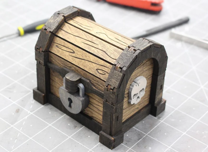
The results speak for themselves, as you can see in the treasure chest image [Nate] provided. Well worth the effort to get this parameter right. We do enjoy laser cutting and engraving things. If you are cutting and don’t have air assist, you really need to hack up something.


“and increase your chances of nailing your boxes on the first cut.”
As someone who works in a cabinet shop, I enjoyed the pun!
Accurate joinery should decrease the chances of nails!
I really dislike using nails. I use screws whenever possible.
So for me, it would be “increase your chances of screwing your box on the first cut”.
Which is far more appropiate for me anyway….
If you want to do it there’s probably a setting for it in lightburn. License management is a pain in the ass though
what is free linux softweare for laser cut?
That depends on your lasercutter. If your cutter has an interface to upload Gcode there are inkscape plugins to generate them. You can draw in inkscape or load dxf, svg or many other formats into it. Often enough the software that comes with the laser is perfectly happy running in wine.
The inkscape cam plugin is abadonware at this point, no work for years
I believe RDWorks is free and runs on linux, it’s also high functionality (I don’t use it, though).
I’m not a fan of plugins for this purpose. The functionality of LightBurn (and, I believe, RDWorks) is so high and so well tested that it’s not worth the time and effort to use workarounds.
A LightBurn license is good for 2 computers, and lets you use the software in perpetuity after the license expires (in a year). The license is essentially for updates and bug fixes, and right now the software is rock solid. It’ll also auto-configure itself if it recognizes the type of laser cutter, and that bit alone can save you an afternoon of fiddling with settings.
Laserweb works to generate and stream gcode to a machine
I made an enhanced test cut model for dialing in your laser’s kerf. The model has a removable inner piece that you can test fit against the slot cuts on the edge to determine exactly the cut width to match a finger join, on one try.
(One test piece will allow you to find the correct measurement, instead of the test piece from the article that has to be cut many times to be dialed in.)
Also, my test model has cut circles of various diameters, so you can quickly identify the best hole for your (for example) 6mm magnets for a good press-fit into acrylic, or screw hole for tapping the acrylic.
https://github.com/OpticsBench/laser-cut-optics-bench/blob/master/Basic/CutTest.dxf
On the subject of finger joins, it’s best to *not* put the tab geometry into your design directly, but rather make it as separate rectangles that when cut will form the tab shapes.
Supposing you have a straight-line edge that needs to be a series of tabs to fit into a mating series of holes. Instead of making the edge a square-wave of tabs, it’s better to keep the existing edge and add extra rectangles (separately cut items) that when cut will result in the square-wave edge.
Having the cuts be extra rectangles will allow you to easily go back and adjust the tab (or space) width easily, without having to change the edge of your design. It’s much *much* easier to select and resize a separate rectangle than it is to adjust the crenellated edge of a larger piece.
Can you just cut a 1″ square? Measure it with calipers and compare to find the kerf?
Only one cut required.
Yes and no. You also need to measure the hole and to determine where the kerf is relative to the cut path, because you might want the piece accurate or the hole accurate.
Also, the edges will be sloped. The laser comes to a point at the top surface of the material and expands after, which means the sides of the cut will be slightly angled. The angle is enough that I couldn’t make a 3-D block puzzle by gluing cut pieces, although jigsaw puzzles seem to work well.
The kerf at the top of the material is smaller than the kerf at the bottom, and we’re measuring very tiny differences so all of these issues come to play.
The best results come from “dialing in” your tab and slot by trial and error, then using that measurement for future projects that use that exact material and thickness.
That’s why when cutting thicker materials I usually set the focal point of the laser down in the center of the material (adjust the Z if you’re fixed focus like on a k40). Gives you a triangular cross section on the edge, but top and bottom kerf is symmetrical
That depend on what precision you want. You usually want to know that value inside of ~5/100 mm. I’m not confident I can measure that on the burned, not straight edge of a piece of wood.
Not one square, but 10.
Make a row of 10mm squares (so 100mm x 10mm). Cut them out, line them back up and measure the total length. With a kerf of zero, they’ll be exactly 100mm, with the typical laser kerf of 0.16 you’ll measure about 98.4mm.
Working backwards measure the cut pieces, get the difference to 100mm, divide by 10, there’s your kerf.
One further note on laser kerf: Hit the “pulse” button and look at the resulting hole with a graticle, this will tell you the kerf directly:
https://hackaday.io/project/5283/gallery#c85d04c33c698b43a7123423c25ebd64
Next you need to find out where the kerf is relative to the cut path. You can do this by cutting a hole, seeing which drill bit shank fits into the hole, and measuring the shank with a micrometer.
Some laser cad software has the ability to compensate for the kerf. You set it as being on the inside or outside of the cut path (or somewhere in between, as was the laser in the local hackerspace) and then you can make *very* accurate cuts, depending on if you want the piece accurate or the hole accurate.
One day you’ll discover lasers have bevels.
HAD says don’t do trial and error to determine kerf, then links to an article that uses trial and error. Keep up the good work, HAD.
Here’s a better instructable that gets you the kerf in one go: https://www.instructables.com/How-to-Adjust-for-Wood-Thickness-and-Kerf-on-a-Las/.
I’ve always been tempted by a laser cutter, but I have an (ir)rational fear of lasers – seen too many near disasters in “safe” laser environments to put one in my garage. Shame, because this looks like fun.