
Modern insulin pumps are self-contained devices that attach to a user’s skin via an adhesive patch, and are responsible for administering insulin as needed. Curious as to what was inside, [Ido Roseman] tore down an Omnipod Dash and took some pictures showing what was inside.
These devices do quite a few things. In addition to holding a reservoir of insulin, they automatically insert a small cannula (thin tube) through the skin after being attached, communicate wirelessly with a control system, and pump insulin through the cannula as needed. All in a sealed and waterproof device. They are also essentially disposable, so [Ido] was curious about what kind of engineering went into such a thing.
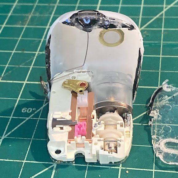
The teardown stops short of identifying exactly how all the mechanisms inside work, but [Ido] was able to learn a few interesting things. For example, all of the mechanical functions — inserting the cannula with the help of a needle (and retracting the needle afterwards) and pumping insulin — are all accomplished by one motor and some clever mechanical engineering.
The electronics consist of a PCB with an NXP EX2105F 32-bit Arm7 microcontroller, a second chip that is likely responsible for the wireless communications, three captive LR44 button cells, and hardly a passive component in sight.
The software and communications side of an insulin pump like this one has had its RF communications reverse-engineered with the help of an SDR, a task that took a lot more work than one might expect. Be sure to follow that link if you’re interested in what it can take to get to the bottom of mystery 433 MHz communications on a device that isn’t interested in sharing.


There’s a great teardown video from 2016 here https://www.youtube.com/watch?v=e2MQUUkubgs that goes into more detail and figures out how the mechanism works.
How did I know who that was going to be :)
I took a couple of these apart a few years ago when I was working for a company that was working on a CGM system that incorporated sensors into the cannula. These things are pretty neat. The “motor” is a piece of nitinol wire that is attached to a ratchet mechanism. The wire is heated and causes it to contract and extends when cooled advancing the mechanism.
The motor turns a wheel which releases a latch that causes the cannula and needle to spring forward and down to implant it in the body. The needle then retracts into the body so only the flexible plastic cannula is still in. As the motor continues to rotate it advances a screw which pushes the piston on the internal syringe. At this point it acts as a unidirectional stepper as each actuation of the wire dispenses a known amount of insulin.
Well there it is: https://youtu.be/e2MQUUkubgs?t=647
One of the first things I spotted on the PCB is (what looks like) a gazillion test points. Test, test, test…
A far distant cousin in the family of “one motor to rule them all” is the Furby.
Could be used as test points but look more like vias, especially the ones on the outside perimeter. Test points are typically solid pads. With the volume, probably were in-circuit tested.
I remember taking apart my Furby for the first time. I was a little disappointed as I expected to harvest many little motors. Even the motor itself didn’t have a full casing as it was one of those motors with open casing to save costs. I remember they sold for a lot of money back then. They must have made a lot of profit.
I get an IV every six months, and a bunch more in 2019. At some point I noticed the IV doesn’t go through the machine that controls it. So a solenoid that controls the flow in the tube.
In 2020 I spent several weeks hooked up to an IV (cancer treatment); the line was threaded through the pump, but wasn’t interrupted by it. Instead, the pump moved fluid by “kneading” the line, like peristalsis. A flow sensor was attached to the line higher up, and worked optically (had to wrap it in aluminium foil when I took a walk outside because sunlight made the sensor go nuts). An interesting way to improve the old system that was purely based on gravity, and restricting the flow, without completely replacing it. For all the issues it had I was glad to have it. My dad used to be a nurse and told me that before those pumps, patients basically had to remain in bed for as long as they had the IV in.
Far cry from the days where you squished the tube to half fill it and counted the number of drips to set up the rate with a little slider that crushed the line.
Amazing how simple this design is, it reminds me of children’s toys that are built down to a price. It’s worth noting that these are still extremely expensive and most insurance companies in the US will not cover them.
One-motor systems are the best : When you want to do always the same movements in a sequence, doing it with one motor is the best mechanical design !
Not always. If your thing is not disposable, and it’s a one off, multiple motors and computer control means it can be built, designed, and upgraded by an average maker without advanced mechanical skills which are way harder to learn than coding. Especially for literal one offs where you might be using 3D printing. A wire doesn’t care if it’s bent, a belt might crap out just because it has the wrong tension.
Motors are often not the thing that fails, so more gears and cams is more to go wrong. Simple mechanical stuff can be insanely reliable, but that’s only because someone really knew what they were doing and used good materials.
Then again, there are equivalents in electronics to grinding gears, and I see them way too much, but at least they don’t require spatial intelligence to debug, it’s mostly stuff you can learn without oto.much effort.
While there is an elegance I really like to the one motor systems it is definitely not so universally ‘the best’. Even if the sequence is always identical the mismatch between the required torque/speed at the actuator from the motor between steps A, B, C can mean the linkages get too heavy, complex and fragile compared to simply putting another motor in better suited to the job varied jobs and the electronics to control them in sequence.