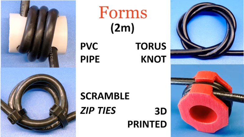
Most ham radio operators will build an antenna of some sort when they first start listening or transmitting, whether it’s a simple dipole, a beam antenna like a Yagi, or even just a random wire vertical antenna. All of these will need to be connected feedline of some sort, and in the likely event you reach for some 50-ohm coax cable you’ll also need a balun to reduce noise or unwanted radiation. Don’t be afraid of extra expenses when getting into this hobby, though, as [W6NBC] demonstrates how to construct an “ugly balun” out of the coax wire itself (PDF).
The main purpose of a balun, a contraction of “balanced-unbalanced” is to convert an unbalanced transmission line to a balanced one. However, as [W6NBC] explains, this explanation obscures much of what baluns are actually doing. In reality, they take a three-wire system (the coax) and convert it to a two-wire system (the antenna), which keeps all of the electrical noise and current on the shield wire of the coax from interfering with the desirable RF on the interior of the coax.
This might seem somewhat confusing on the surface, as coax wires only have a center conductor and a shield wire, but thanks to the skin effect which drives currents to the outside of the conductor, the shield wire effectively becomes two conductors when taking into account its inner and outer surfaces. At these high frequencies the balun is acting as a choke which keeps these two high-frequency conductors separate from one another, and keeps all the noise on the outside of the shield wire and out of the transmitter or receiver.
Granted, the world of high-frequency radio circuits can get quite complex and counter-intuitive and, as we’ve shown before, can behave quite unexpectedly when compared to DC or even mains-frequency AC. But a proper understanding of baluns and other types of transformers and the ways they interact with RF can be a powerful tool to have. We’eve even seen other hams use specialty transformers like these to make antennas out of random lengths and shapes of wire.
Thanks to [Zane] for the tip!


Coiled coax makes for generally terrible baluns, and in some cases the interwinding capacitance can combine with the inductance of the coil to actually produce a series resonant circuit that is useless. At best they are effective over a relative small ( and mostly uncertain) frequency range, and they are mostly used in a pinch. Look up K9YC’s ferrite balun designs that actually work.
This!
I second, and agree, these poor “baluns” can be swept with a NanoVNA and witness the poor CMC attenuation and the narrow uneven bandwidth. The correct ferrite mix will make the best ‘balun’ core vice air core, the number of turns depend somewhat on the band of use due to resonance. Typically both a choke/s and a balun are employed for best result…
I have a book from 1980s that shows, how to properly make baluns with ferrites for lower RF bands and with coax for higher ones. IIRC, the coax ones used half-wave and quarter-wave lengths arranged to form either transformer or series of standing wave traps to match everything. I think one design called for looping a piece of coax to shift phase or something. I’m not sure about the details, because I read it ~10 years ago.
The skin effect – 3 wire coax part is total BS. Most of the rest of the video too.