The Component Abuse Challenge is dragging all sorts of old, half-forgotten hacks out of the woodwork, but this has got to be the most vintage: [KenS] started using a transformer as a variable choke on his speakers 55 years ago.
The hack is pretty bone-dead simple. A choke is an inductor in an audio (or any other) circuit designed to, well, choke off higher-than-desired frequencies. We featured a deep dive a few years back if you’re interested. An inductor is a coil of wire, usually (but not necessarily) wound around a core of iron or ferrite. A transformer? Well, that’s also a coil of wire around a core… plus an extra coil of wire. So when [KenS], back in his salad days, had a tweeter that a was a little too tweety, and no proper choke, he grabbed a transformer instead.
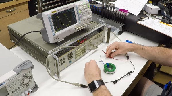
This is where inspiration hit: sure, if you leave the second winding open, the transformer acts like a standard choke. What happens if you short that second winding? Well, you dampen the response of the first winding, and it stops choking, to the point that it acts more like a straight wire. What happens if you don’t short the second winding, but don’t leave it wide open? [KenS] stuck a potentiometer on there, and found it made a handy-dandy variable choke with which to perfectly tune the tone response of his speakers. Changing the resistance changes the rate at which high frequencies are choked off, allowing [KenS] to get the perfect frequency response with which to rock out to Simon & Garfunkel, The Carpenters and The Guess Who. (According to the Billboard Top 100 for 1970, those are who you’d be listening to if you had conventional tastes.)
While we can’t say the transformer is really being tortured in this unusual mode, it’s certainly not how it was designed, so would qualify for the “Junk Box Substitutions” category of the Component Abuse Challenge. If you’ve made similar substitutions you’d like to share, don’t wait another 55 years to write them up– the contest closes November 11th.
Transformer image: Hannes Grobe, CC BY-SA 4.0.