As part of our Op-Amp Challenge we’re seeing a wide diversity of entries showcasing the seemingly endless capabilities of these extremely versatile parts. Another one comes from [Joseph Thomas], who when faced with the need to measure the properties of an automotive spark plug, came up with a precision peak detector to hold on to the energy level used when firing it.
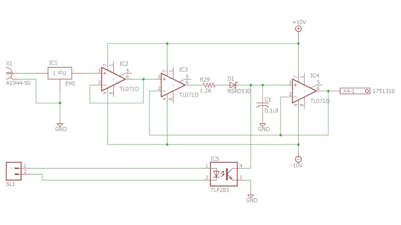
It starts with an op-amp buffer feeding a diode and capacitor. The capacitor is charged through the diode and holds the level, which can be read through another op-amp. Finally there’s an opto-isolated transistor to discharge the capacitor before a fresh reading is taken.
It’s a simple enough circuit but a very effective one. The op-amps used are bit old-school FET devices, but aside from the high impedance input their performance is hardly critical. Yet another op-amp circuit to hold in reserve should you ever need to perform this task.


Aside form “complaining” about terminology (this is not peak power or peak energy measurement, this is peak voltage measurement gizmo :)), why do you need 3 OpAmps
You can probably get most of what you need from just one that is configured as an “ideal diode” (search google for “Precision_rectifier”. As configured you get fairly significant voltage drop on the diode
Input impedance will still be high (leakage current is much smaller from what your spark plug expects to get), and the rest of your circuit that measures value on the C is probably much higher impedance then the R in your RC low pass section
Would love to see the rest of the project – measuring spark plugs sounds interesting :)
The neg. feedback path for IC3 is taken from the IC4 buffer, after the diode, so there will not be an error from the diode voltage drop.
The point still remains. A simple “Ideal diode” op amp configuration with a cap and mosfet (i see no need for opto-isolation) would likely be enough. Past that, if more is required, here are some better circuits. (all of these can have mosfets added to reset the circuit as well)
https://www.analog.com/en/technical-articles/ltc6244-high-speed-peak-detector.html
The clever bit is the feedback from the output amplifier that cancels out the diode and resistor in the middle, so the output rises to the sampled voltage regardless of what IC3 output has to do to get it there. I’ve done this circuit before but only took the feedback past the diode to avoid loop stability issues, but in hindsight that was an unfounded concern and this would have been better because it also eliminates the input offset of the final buffer amp.
The concern is that if there is a significant delay in the circuit by R29, so IC3 will see a large differential input and can shoot up to the rail at full open loop gain, which may cause it to latch up. It takes time to recover, so it can overshoot the voltage even when IC4 is telling it enough is enough.
Though of course the peak is a short transient and the op-amp has a slew rate, it won’t reach the rail before the peak is over, but at the same time the output won’t come down quickly so there’s bound to be some over or undershoot. If you really dig deep into it, it’s a balancing act between the low-pass filter RC network and the speed and propagation delays of the op-amps.
Me, I would just borrow some fast ADC module that’s sampling at 1-2 MHz, or even buying the hardware outright. It costs the same hiring a person to spend two weeks finessing and calibrating the design if you want it accurate. If you can accept some uncertainty and only need consistency for comparison between measurements taken with the same hardware, this is more than fine.
*this circuit is more than fine
I missed to recognized that the “middle” op amp (IC3) is getting negative feed back from the output buffer! Valid point!
What would be benefits of doing it that way instead of doing a often seen/well understood version many call “precision rectifier” or an “ideal diode” (negative feedback from diode and C?
I agree, delays in the loop introduced by IC4 (buffer) are bound to cause some difficult to predict transient states.
Also, I suppose that IC2 (the first buffer) is not required, but does not hurt (much) as it’s decoupled form the rest. Might introduce some input offset based errors, but I don’t think it’s overly critical in this use case
The “precision rectifier” only compensates for its own output. That is common in designs that may be mixed and matched, so each functional block or module can only be concerned with its own inputs and outputs. That is also why it is used as a standard textbook example – and abstraction of the principle.
This is a good, cheap way to make a decent, if slow, peak detector. It’s good that the pulses it measures are about a millisecond long: it would undershoot much shorter ones.
To speed it up, C1 could be reduced (it’s very large for the application). To address Dude’s concern about saturation and latchup, a diode can be added from IC3-2 (the feedback line), to the junction between R29 and D1, which will speed it up further.
I wonder what the driver is to make the testing run at the sedate 3 seconds per spark. Ordinary driving runs spark plugs at dozens of that rate. A year of 24×7 testing here equates to just 7,000 miles of driving.
Maybe they’re using enormous energies to artificially erode the electrodes.
Again that basic mistake power vs voltage. Seems some never learn.
This circuit is a quite bog standard (voltage) peak detector. I think it’s described in one of the TI application notes I’ve got back form the ’80-ies. Maybe it’s more common to use a BJT or FET to reset the peak detector, but an optocoupler can also get the job done.
IC2 does not do anything. It’s used as a buffer, but it’s output goes into IC3, which is just the same opamp type with the same input impedance.
With a 10V power supply (Approx 8V max output for IC3) and 1k2 for R29, you also limit the charge current for C1 to about 8/1200 = 6mA.
Max Charge rate of C1 6e-3/100e-9 = 6e4 V/s = 0.06V/us, and this seems quite slow for measuring car ignition systems. Usually the sample capacitor is kept as small as possible.
These old school schematics of course still work, but these days, with microcontrollers that have ADC’s that can sample at several MHz, you might as well do the rest in software.
They can sample, but they won’t be accurate at that high sampling rate.
Having pulled my hair out over a similar circuit having a poor slew rate, I can highly recommend the following circuit from Elliot sound products:
https://sound-au.com/appnotes/an014-f3.gif
The output climbs to the sampled voltage independent of what the IC3 output has to do to get there thanks to a smart bit of feedback from the output amplifier that cancels out the diode and resistor in the middle. This circuit was previously completed by me, but I just passed the feedback beyond the diode in order to prevent loop stability problems. Looking back, it was a misplaced worry, and this would have been preferable because it also removes the input offset of the final buffer amp.
The issue is that IC3 might sense a huge differential input and could shoot up to the rail at maximum open loop gain, which could lead to it latching, if there is a considerable delay in the circuit caused by R29. anyone tell me i’m right.