Carbon Fiber And Kevlar Make This Linear Actuator Fast And Strong

When it comes to the “build versus buy” question, “buy” almost always wins. The amount of time you have to put into building something is rarely justified, especially with a world of options available at the click of a mouse.

That’s not always the case, of course. These custom-made linear actuators are a perfect example of when building your own wins. For a planned ball-juggling robot, [Harrison Low] found himself in need of linear actuators with long throw distance, high speed, and stiff construction. Nothing commercially available checked all the boxes, so he set out to design his own.

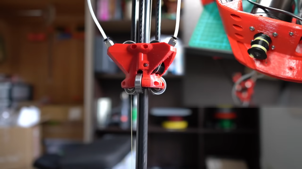
A few design iterations later, [Harrison] arrived at the actuators you see in the video below. Built mainly from carbon fiber tubing and 3D-printed parts, the actuators have about 30 centimeters of throw, and thanks to their cable-drive design, they’re pretty fast — much faster than his earlier lead screw designs. The stiffness of the actuator comes by way of six bearings to guide the arm, arranged in two tiers of three, each offset by 60 degrees. Along with some clever eccentric spacers to fine-tune positioning, this design provides six points of contact that really lock the tube into place.

The cable drive system [Harrison] used is pretty neat too. A Kevlar kite string is attached to each end of the central tube and then through PTFE tubes to a pulley on an ODrive BLDC, which extends and retracts the actuator. It’s a clever design in that it keeps the weight of the motor away from the actuator, but it does have its problems, as [Harrison] admits. Still, the actuator works great, and it looks pretty cool while doing it. CAD and code are available if you want to roll your own.

These actuators are cool enough, but the real treat here will be the ball juggler [Harrison] is building. We’ve seen a few of those before, but this one looks like it’s going to be mighty impressive.

Continue reading “Carbon Fiber And Kevlar Make This Linear Actuator Fast And Strong”

How To Install Mac OS On The Nintendo Wii

What if you could run Mac OS on a Nintendo Wii game console? That’s probably not a thought that has occurred to many Wii owners or Mac OS users, but that is no excuse not to give it a try, as [Michael] handily demonstrates in a recent video by running Mac OS 9 on a Nintendo’s legendary console. The first major issue is what anyone who has ever tried to put a Hackintosh together knows: just because a target system runs the same CPU architecture can you necessarily install Mac OS (or OS X) for Intel x86 on any Intel x86 system. The same is true for the Wii with its PowerPC CPU and running Mac OS 9 for PowerPC on it.

In order to make this work, a workaround is employed, which uses the fossilized Mac-on-Linux project to run PowerPC Mac OS essentially on Linux for the Wii. This is a kernel module which allows Mac OS to run at basically native speeds on Linux, but it being a Linux kernel module, it meant that [Michael] had to hunt down the correct kernel to go with it. After creating an SD card with a functioning bootloader, he was able to boot into Wii Linux with MoL enabled, and try to install Mac OS.

OS X didn’t work for some reason, but Mac OS 9 did work, albeit with severe font rendering and audio glitches. All of which seems to come down to that while it is possible to get Mac OS running on the Wii, doing so is definitely more for the challenge and experience. By the way, if all this sounds a bit familiar, it’s because [Michael] referenced the Mac-on-Wii work that [Dandu] did last year to make this latest iteration happen.

Continue reading “How To Install Mac OS On The Nintendo Wii”

LoRa Goes To The Moon

LoRa is a communications method that allows for long range radio contacts to be made using typically low-powered devices. This shouldn’t be surprising given that LoRa is short for “long range” which typically involves distances on the order of a few kilometers. However, a group of students are taking the “long range” moniker to the extreme by attempting to send and receive a signal with a total path of around 768,000 kilometers by using some specialized equipment to bounce a LoRa signal off of the moon and receive it back on Earth.

Earth-Moon-Earth (EME) communications are typically done by amateur radio operators as a hobby, since the development of communications satellites largely rendered other uses of this communication pathway obsolete. A directional antenna and a signal typically on the order of 1 kW are often used to compensate for the extremely high path losses. Using LoRa, which makes use of chirp spread spectrum modulation, they hope to reduce this power requirement significantly. The signals are being generated and received on a set of HackRF One devices fed into a series of amplifiers, and the team is also employing a set of large dish antennas, one in New Jersey and another in Alaska, to send and receive the messages.

The software used is the open-source SDRAngel which is useful for controlling the HackRF and moving the LoRa signal up to 1296 MHz. Normally LoRa is operated on an unlicensed band, but this method allows for finer control of not only frequency but also bandwidth, which helps reduce the impacts of path loss. Right now they have not yet completed their contacts with the Alaska station (partially due to that antenna being covered in snow) but we hope to hear more news in the future. In the meantime, take a look at some more traditional long-range communications using this protocol with more manageable-sized antennas.

Image courtesy of NASA, Public domain, via Wikimedia Commons

New Drivers For Ancient Webcam

For those of us who are a little older, the 90s seem like they were just a few years ago. The younger folks might think that the 90s were ancient history though, and they might be right as we’ve been hearing more bands like Pearl Jam and The Offspring playing on the classic rock stations lately. Another example of how long ago the 90s were is taking a look at the technological progress that has happened since then through the lens of things like this webcam from 1999, presuming you load up this custom user space driver from [benjojo].

Thankfully the driver for this infamous webcam didn’t need to be built completely from scratch. There’s a legacy driver available for Windows XP which showed that the camera still physically worked, and there’s also a driver for Linux which was used as a foundation to start working from. From there a USB interface was set up which allowed communication to the device. Not a simple task, but apparently much easier than the next steps which involve actually interpreting the information coming from the webcam. This is where a background in digital signal processing is handy to have. First, the resolution and packet size were sorted out which led to a somewhat recognizable image. From there a single monochrome image was pieced together, and then after deconstructing a Bayer filter and adding color, the webcam is back to its former 90s glory.

[benjojo] has hosted all of the code for this project on a GitHub page for anyone who still has one of these webcams sitting around in the junk drawer. The resolution and color fidelity are about what we’d expect for a 25-year-old device that predates Skype, Facebook, Wikipedia, and Firefox. And, while there are still some things that need to be tweaked such as the colors, white balance, and exposure, once that is sorted out the 90s and early 00s nostalgia is free to flood in.

Op-Amp Challenge: Reliable Peak Power Measurement

As part of our Op-Amp Challenge we’re seeing a wide diversity of entries showcasing the seemingly endless capabilities of these extremely versatile parts. Another one comes from [Joseph Thomas], who when faced with the need to measure the properties of an automotive spark plug, came up with a precision peak detector to hold on to the energy level used when firing it.

It starts with an op-amp buffer feeding a diode and capacitor. The capacitor is charged through the diode and holds the level, which can be read through another op-amp. Finally there’s an opto-isolated transistor to discharge the capacitor before a fresh reading is taken.

It’s a simple enough circuit but a very effective one. The op-amps used are bit old-school FET devices, but aside from the high impedance input their performance is hardly critical. Yet another op-amp circuit to hold in reserve should you ever need to perform this task.

NASA’s Voyager Space Probe’s Reserve Power, And The Intricacies Of RTG-Based Power Systems

Launched in 1977, the Voyager 1 and 2 space probes have been operating non-stop for over 45 years, making their way from Earth to our solar system’s outer planets and beyond. Courtesy of the radioisotope thermoelectric generators (RTGs) which provided 470 W at launch, they are able to function in the darkness of Deep Space as well as they did within the confines of our Sun-lit solar system. Yet as nothing in the Universe is really infinite, so too do these RTGs wear out over time, both from natural decay of their radioactive source and from the degradation of the thermocouples.

Despite this gradual drop in power, NASA recently announced that Voyager 2 has a hitherto seemingly unknown source of reserve power that will postpone the shutdown of more science instruments for a few more years. The change essentially bypasses a voltage regulator circuit and associated backup power system, freeing up the power consumed by this for the scientific instruments which would otherwise have begun to shut down years sooner.

While this is good news in itself, it’s also noteworthy because the Voyager’s 45+ year old Multi-Hundred Watt (MHW) RTGs are the predecessor to the RTGs that are still powering the New Horizons probe after 17 years, and the Mars Science Laboratory (Curiosity) for over 10 years, showing the value of RTGs in long-term exploration missions.

Although the basic principle behind an RTG is quite simple, their design has changed significantly since the US put a SNAP-3 RTG on the Transit 4B satellite in 1961.

Continue reading “NASA’s Voyager Space Probe’s Reserve Power, And The Intricacies Of RTG-Based Power Systems”

Exploring Woodworking Mysteries With Strain Gauges And Raspberry Pi

If you’re not a woodworker, you might not have heard of the “45-degree rule.” It goes like this: a clamp exerts a force that radiates out across a triangular region of the wood that forms a right angle — 45 degrees on each side of the clamp’s point of contact. So, to ensure that force is applied as evenly as possible across the entire glue joint, clamps should be spaced so that these force triangles overlap. It’s a handy rule, especially for the woodworker looking to justify the purchase of more clamps; you can never have too many clamps. But is it valid?

Myth busted?

The short answer that [ari kardasis] comes up with in the video below is… sort of. With the help of a wonderfully complex array of strain gauges and a Raspberry Pi, he found that the story isn’t so simple. Each strain gauge lives in a 3D printed bracket that spaces the sensors evenly along the wood under test, with a lot of work going into making the test setup as stiff as possible with steel reinforcement. There were some problems with a few strain gauges, but once he sorted that out, the test setup went into action.

[ari] tested clamping force transmission through pieces of wood of various widths, using both hardwoods and softwoods. In general, he found that the force pattern is much broader than the 45-degree rule suggests — he got over 60 degrees in some cases. Softwoods seemed to have a somewhat more acute pattern than hardwoods, but still greater than the rulebook says. At the end of the day, it seems like clamp spacing of two board widths will suffice for hardwoods, while 1.5 or so will do for softwoods. Either way, that means fewer clamps are needed.

A lot of woodworking is seat-of-the-pants stuff, so it’s nice to see a more rigorous analysis like this. It reminds us a lot of some of the experiments [Matthia Wandel] has done, like load testing various types of woods and glues.

Continue reading “Exploring Woodworking Mysteries With Strain Gauges And Raspberry Pi”