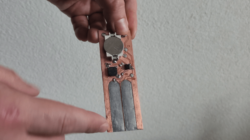
Around the Hackaday bunker, any plant other than a cactus has a real chance of expiring due to thirst. Perhaps we should build some of [MakersFunDuck]’s Moisture Duck boards. As you can see in the video below, the simple PCB with an ATtiny13A tells you when it is time to water the plants. The video also covers several exotic methods of determining the watering status, some of which are pretty complex.
The board is simple because the operation of the device is simple. A fixed resistor creates a voltage divider with the soil, and dry soil has higher resistance than moist soil. A pot sets a threshold, and the microcontroller measures the voltages.
Of course, if you can’t remember to water the plants, you probably can’t remember to change batteries either. So the device sleeps most of the time, and only wakes up every eight seconds to conserve battery. It would be nice to alarm on a low battery, and, honestly, we would probably have made the sleep time longer.
The video covers how he minimizes corrosion, but we aren’t sure how well the board will survive in damp soil, but with a little protection, it might last a while. Besides that, you could probably just consider them almost disposable.
If you are really lazy, you can also automate the actual watering. You can even build that into a smart flower pot.


To minimize corrosion, use an AC signal instead of DC. Do a quick measurement (as fast as you can) and then do the same measurement with swapped pins.
Corrosion is not just a waste of the board, but all these dissolved metal ions can’t be good for the plant.
To eliminate corrosion, insulate the leads and measure the capacitance between.
I can’t imagine that would work, because someone would have done it by now.
The video talks about capacitive sensors, in fact.
They do a quick measurement every 8 seconds, so electrochemical corrosion should be limited. Regular corrosion can only be prevented by sealing the electrodes and using capacitive measurement.
By the way I’d think that soil humidity changes on a timescale of minutes or longer, so I’d extend the measurement interval accordingly.
I wish people would put a PDF or image of their schematics in the repository, instead of just KiCad files.
+1
If you’re even remotely interested in hardware design, especially open hardware, then frankly you should already have KiCad installed and ready to go.
What if you’re interested in hardware design, but have another program installed ?
What if I am only interested in collecting interesting projects to build them “when I have time”?
+1
I have.. but not on my phone. And even on PC, I feel a bit uneasy opening untrusted kicad project files.
Ya ok, except for us professionals. That’s some serious small thinking. Your comment is no different than saying if you’re even remotely interested in programming you should have Java installed and ready to go.
They used to make these with transistors.
> honestly, we would probably have made the sleep time longer.
The design uses the watchdog timer on the ATTiny13A, and 8 seconds is already the maximum duration.
Should take not more than two or three lines of additional code to do the measurement only every
100th time (still more than enough) and return to sleep otherwise.
A tensiometer tube is not really reliable since it forms air bubbles out of dissolved gasses, which have to be pumped out periodically. You never know if the soil is wet or the tube is full of air.
Another cheap version of the tensiometer sensor is to cast two carbon electrodes into a block of gypsum and measure the resistance between the two. Again, AC works better.
You make a simple resistor divider, say 1/2 Vcc, and connect one electrode through a large-ish capacitor (about 20 uF bipolar electrolyte) to the center node of the divider. Then the other electrode is connected again through a capacitor to your MCU output pin. This gives you galvanic isolation and greatly slows down corrosion.
You run a ~1 kHz square wave through it and measure synchronously at high and low voltage levels how much the voltage at the divider swings up and down. Repeat for a couple hundred cycles and count the average. Then you calculate what the equivalent resistor needs to be to cause that deviation, subtract the impedance of your series capacitors, and you get the resistance of and between the two carbon rods.
The gypsym works as a tensiometer because it picks up and loses water by osmotic pressure. It’s a known medium between the electrodes, so the resistance vs. water content can be calibrated independent of the soil surrounding it. It will slowly dissolve away and expose the electrodes, so the sensor is disposable, but it works reasonably well for a couple years. It’s also non-toxic so the spent sensor can be left in the ground by simply yanking the wires away.
When calibrating the system, you can replace the gypsum sensor with a known resistor to measure and correct for the ESR of the capacitors at the measuring frequency.
To calibrate the system for your flower pot, take the same soil you want to use, bake it dry, and pour it on the sensor inside a container of a known volume – say, one liter. Then you add a measured amount of water, let it soak in for several hours, measure, and repeat until the soil is completely wet. When the soil starts to get completely saturated with water, the resistance of the sensor should drop sharply and level off, which is how you know you’ve over-watered the plant.
>If you are really lazy, you can also automate the actual watering.
heh, that is until you start getting into building your own (reliable) watering solutions.