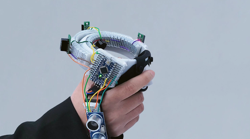
You think of breadboards as being a flexible way to build things — one can easily add components and wires and also rip them up. But MIT researchers want to introduce an actual flexible breadboard called FlexBoard. The system is like a traditional breadboard, but it is literally flexible. If you want to affix your prototype to a glove or a ball, good luck with a traditional breadboard. FlexBoard makes it easy. You can see a short video below and a second video presentation about the system, also.
The breadboard uses a plastic living hinge arrangement and otherwise looks more or less like a conventional breadboard. We can think of about a dozen projects this would make easier.
What’s more, it doesn’t seem like it would be that hard to fabricate using a 3D printer and some sacrificial breadboards. The paper reveals that the structures were printed on an Ender 3 using ePLA and a flexible vinyl or nylon filament. Want to try it yourself? You can!
We know what we will be printing this weekend. If you make any cool prototypes with this, be sure to let us know. Sometimes we breadboard virtually. Our favorite breadboards, though, have more than just the breadboard on them.


Why not just learn how to solder?
Unfortunately, at least in my research no such component any longer exists… Yet why not build a breadboard guided by a huge analog mux, and then do all the routing in software ? For me, messing with the wires has always been the hard part.
That’s actually a thing I’ve been working on for the last few years. I haven’t done a writeup about the recent revision (read: complete redesign) but the concept is basically the same.
https://hackaday.io/project/180394-breadware
BTW the chip you’re looking for is an MT8816 or a CH446Q 8×16 analog crosspoint switch. You need to do some weird stuff to string them together to cover a whole breadboard but all the bigger ones are like $400 each and can only handle really small signals.
Or for really simple stuff you can use the CD4051 8:1 analog multiplexer.
Holy shirt dude. I didn’t know such a thing existed. That’s actually really cool.
It doesn’t look like you’re selling them, so whats the approx BOM $ per board? Just a looking at the picture I estimated in the $20 to $40 range, but that’s without even bothering to count components.
Also, when you say analog routine, is that analog as in direct physical connection, or is it a simulated analog connection?
For example, if I was testing how well a given voltage regulator worked in specific circuit, would this board give me an accurate picture of voltage sags under load and all that? Or am I routing analog *signals* instead of *connections*?
Thanks!
The BOM cost for the new one is like ~$80, that’s including the custom plastic housing and getting breadboard spring clips made to accommodate having RGB LEDs under every row. I probably could get that down quite a bit with some tweaks and volume.
But yeah, the connections are real. Internally, they go through a CMOS switch so there’s some resistance (~45 ohms), but in the code you can set priority for a connection like that super high so it will make as many redundant connections as it can to reduce it.
You can emulate a few signals like you mentioned too, but I would consider a board that worked like that totally cheating.
And in your example, you could do all that measuring on board. It has 4 buffered ADCs (one of them for +-8V), 2 current sensors, and 2 high(ish)-current DACs (one for +-8V, the other for +0-5V.)
Sorry to sound like an ad. But yeah I’ll be selling them pretty soon once I hammer out enough of the bugs.
Anyway, here’s a link to the newest revision
https://hackaday.io/project/191238-jumperless
You mean a FPGA?
Jan, FPGA/CPLD/etc is different. You can control a lot of switches and GPIO for example that way, but you can’t let all sorts of crazy voltages run *through* it, which is why we talk about the Mux (multiplexer).
Wow that looks like a seriously over-engineered solution to a not very common problem. The ultrasonic breakout board hanging off the flexboard made me laugh. It looks pretty janky to me. Soldering stuff together for prototypes isn’t that hard and you can make them much smaller than this board would allow, plus you wouldn’t have lots of breadboard wires hanging about ready to be pulled out at the least convenient moment.
Agree. I mean you can wire stuff together without even soldering. Even solid core wire is flexible. And whoever had a board for cutting bread that was flexible? Why not at least call it something else? I always assumed breadboard was named after a bread cutting board?
Breadboard as a means of constructing circuits comes from a time before mine (but not before the authors of the electronics books in my local public library), when fahnestock clips (https://en.wikipedia.org/wiki/Fahnestock_clip) were screwed into a literal bread cutting board to provide a means for wiring components together without soldering, much to the chagrin of anyone in the household who had some bread to cut. So the principal element of “breadboarding” isn’t the board itself, but the solderless prototyping method. And nobody really knew for sure how “fahnestock” was supposed to be pronounced, since we’d only read about them in books.
A solution waiting for a problem to solve? There’s a lot of that out there.
I can see both sides. Its got a real “I need a problem to solve” kind of college-homework feel to it. But otoh the effort to payoff ratio isn’t bad, since the only components you need are an hour on a 3d printer and an old 50 cent breadboard you’re willing to sacrifice.
Instead of thinking of it as a “flexible breadboard”, think of I more like a flexible component gripper for you string your wires between when prototyping odd shaped circuits.
If you think of it as a technique to use in one-off and as-needed scenarios, and it’s not going to add much time to your prototype building process for such a circuit, and could be more convenient than directly soldering.
Nice idea!
BTW, does anyone know where breadboard contacts can be purchased? I also have ideas to make custom breadboards, but scavenging breadboards is not the best solution to get the contacts…
It’s seriously impossible, I’d spent so much time searching that I eventually 3D modeled them so I can have them custom made for my project.
I made them with a little hole to mount a WS2812C-2020 addressable LED in each one and through hole leads to mount onto a PCB.
I got a bunch of quotes and it’s looking like $1000 for setup and $0.05 each for a MOQ of 10,000. I’ll probably put in an order soon and I’ll sell the clips on Tindie.
But if you want to look into having your own made, the 3D models and drawings for them and the plastic breadboard shell are on Github here:
https://github.com/Architeuthis-Flux/Breadboard3DmodelsJumperless/tree/main
Those who claim something can’t be done are often interrupted by someone accomplishing what was said couldn’t be done.
This is very strange nobody sell them, as they are widely used in breadboards!
I bought a STEMTera board (https://www.stemtera.com), some years ago (it was a kickstarter), and they used some, and even had custom ones (2 poles)… I asked them where they bought them, but they never answered :o(
Anyway, your project is very interesting, I would definitely buy some clips!
My idea is to 1) make breadboards with a larger gap between the 2 parts, to match Arduino Nano space, and other boards (like Rpi Pico), whithout having pins under the board.
Another idea is to create STEMTera-like boards, but with different chips (RP2040, eps32…).
I’m surprised I had never heard of the STEMTera. Maybe I should try asking them again.
I actually just made a quick offshoot project to address that annoying dev-board-covering-pins thing. Slightly different approach though.
https://twitter.com/arabidsquid/status/1661079788101177345?s=20
I got an answer from STEMTerra!
The bas news is they don’t sell the clips.
The good news is they are about to sell new boards, based on new chips!
https://www.tindie.com/products/architeuthisflux/solderable-breadboard-spring-clips/
I thought the main point of breadboards was prototyping. Therefore this set would speak to the need for flexibility in the design process. Once the prototype is right, then the flexible assembly can help in guiding the transition to a more permanent assembly using soldiered components.
I have seen sets with several size boards but not the flexible hinge; that is a productive addition.