Here at Hackaday we really like to feature projects that push the limits of what’s possible, or ones that feature some new and exciting technology that nobody has ever seen before. So what’s so exciting about this single-voltage linear power supply? Honestly, nothing — until you start looking at its thermally compensated current limiting circuit.
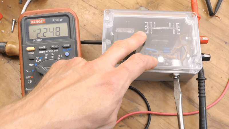
This one is by [DiodeGoneWild], who you’ve really got to hand it to in terms of both the empirical effort he went through to optimize the circuit, as well as the quality of his explanation. The basic circuit is dead simple: a transformer, a full-wave rectifier, an LD1085 adjustable regulator — a low-dropout version of the venerable LM317 — and associated filter caps and trimmer pot to adjust the output between 2.2 and 5.5 volts.
The current limiting circuit, though, is where things get interesting. Rather than use an op-amp, [DiodeGoneWild] chose a simple discrete transistor current-sense circuit. To make it less susceptible to thermal drift, he experimented with multiple configurations of resistors and Schottky diodes over a wide range of temperatures, from deep-freeze cold to hair-dryer-in-a-box hot. His data table and the resulting graph of current versus temperature are works of art, and they allowed him to make sensible component selections for a fixed 250-mA current limit with a reasonably flat thermal response.
As for construction, it’s all classic [DiodeGoneWild], including a PCB with traces ground out with a Dremel and a recycled heat sink. He also dropped a couple of interesting build techniques, like adding leads to turn SMD tantalum caps into through-hole components. The video below shows all the build details along with the exhaustive breadboard testing.
From taking on a potentially risky magnetron teardown to harvesting lasers from headlights, there’s always something to learn from a [DiodeGoneWild] video.


Reading the schematic is rough and understanding the content creator presents its own challenges. But it is a nice effort in linear design. Please remove the YouTube distraction for clarity.
I would have taken a different tack: 1. A switching pre-regulator and current limiter and 2. A linear post regulator with built-in output protection. Fast (switching) and relatively noise free (linear) tandem performance – but yes, a bit more complex. This could be easily extended below zero volts output if you added a charge-pump driven negative reference off the AC mains transformer secondary.
I just realised that I can use an NCP1117 surface mount SOT23 in veroboard, by simply pointing the pins through the holes. They don’t stick very far into the holes, but if you fill the hole up with solder, they seem to work just fine!
The simple circuits often work best the article mentions a dremel to mill out pcb tracks I have done that I now make printed circuits using copper slug tape stick tape on insulating material such ad paxolin and surface mount parts the glue on tape is good withstands soldering and easy to modify circuit many years ago a commercial product called cirkit tape was available I gave up etching circuits years ago I notice that printed circuits go back to world war 2 when germans and Americans used ceramic sheets with silver traces on them the Germans fitted ceramic tube capacitors on them with no or very short leads the first surface mount parts in their fug 10 radio used in aircraft
Oh no, Danyk and his Eenngglliisshh. :-D
(He’s known under this name on his web+forum)
Yeah, I genuinely would appreciate a “too long, didn’t watch” forum post breakdown of the video.
Also shoutout to YouTube for removing the ability for viewers to easily cobble together video subtitles suggestions to the uploader back in 2020, sure would’ve been helpful here.
https://www.theverge.com/2020/7/31/21349401/youtube-community-captions-deaf-creators-accessibility-google