High-Resolution MIDI Controller

For an older standard, MIDI has remarkable staying power in the music industry. It remains the de facto digital interface between computers and instruments thanks to its open nature, but its age does show a little bit. Sending control change (CC) messages, for example, was originally designed to fit within seven bits, which doesn’t give particularly fine resolution compared to more capable modern computers. To work around that, a fourteen-bit message is possible, doubling the resolution, and this MIDI interface uses this larger amount of data to send these high-resolution CC messages.

The 14-bit messages are actually fairly well documented but are a bit obscure, with very limited hardware support. To that end, [Gero] set about building this control interface to solve that problem. It’s made up of only eight knobs, each of which is mapped one-to-one to a parameter on the computer, allowing the interface to feel more like an analog device where the knob corresponds directly to a change in an aspect of the sound. The platform is built around a Teensy 4.0 and some multiplexers to handle all of the knobs, with the open source software available for anyone to use to modify their actions. [Gero] was aiming for high fidelity for all aspects of this controller, not just the improved digital resolution, and made a number of other improvements to it as well like re-greasing the potentiometer knobs and a custom 3D printed enclosure.

All of the software is available for use, as well as the files to print the case. [Gero] is also working on a PCB to make the construction of the device a little more streamlined, but for now, it requires a bit of soldering off-the-shelf parts together. The MIDI standard is open as well, which allows for a lot of innovation in the creation of musical instruments from unique hardware. This project builds a MIDI synthesizer with parts from a Sega Genesis.

Linear Power Supply’s Current Limiter Is A Lesson In Simplicity

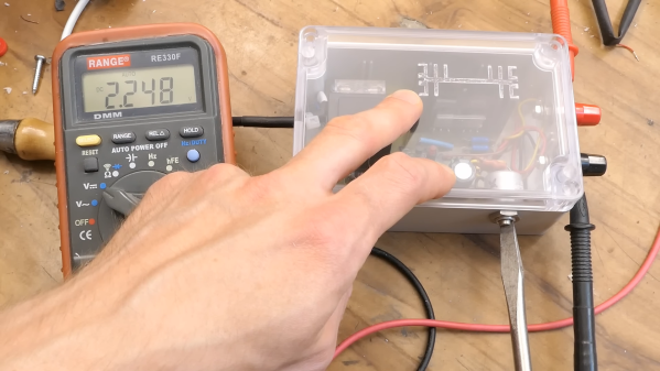
Here at Hackaday we really like to feature projects that push the limits of what’s possible, or ones that feature some new and exciting technology that nobody has ever seen before. So what’s so exciting about this single-voltage linear power supply? Honestly, nothing — until you start looking at its thermally compensated current limiting circuit.

This one is by [DiodeGoneWild], who you’ve really got to hand it to in terms of both the empirical effort he went through to optimize the circuit, as well as the quality of his explanation. The basic circuit is dead simple: a transformer, a full-wave rectifier, an LD1085 adjustable regulator — a low-dropout version of the venerable LM317 — and associated filter caps and trimmer pot to adjust the output between 2.2 and 5.5 volts.

The current limiting circuit, though, is where things get interesting. Rather than use an op-amp, [DiodeGoneWild] chose a simple discrete transistor current-sense circuit. To make it less susceptible to thermal drift, he experimented with multiple configurations of resistors and Schottky diodes over a wide range of temperatures, from deep-freeze cold to hair-dryer-in-a-box hot. His data table and the resulting graph of current versus temperature are works of art, and they allowed him to make sensible component selections for a fixed 250-mA current limit with a reasonably flat thermal response.

As for construction, it’s all classic [DiodeGoneWild], including a PCB with traces ground out with a Dremel and a recycled heat sink. He also dropped a couple of interesting build techniques, like adding leads to turn SMD tantalum caps into through-hole components. The video below shows all the build details along with the exhaustive breadboard testing.

From taking on a potentially risky magnetron teardown to harvesting lasers from headlights, there’s always something to learn from a [DiodeGoneWild] video.

Continue reading “Linear Power Supply’s Current Limiter Is A Lesson In Simplicity”

Icicle Patterns With Custom Gantry

[Cranktown City] uses a number of custom-built linear rails used as gantries for various tools in the shop. The first is on a plasma cutter, which is precise but difficult to set up or repair. Another is for mounting a camera, and while it is extremely durable, it’s not the most precise tool in the shop. Hoping to bridge the gap between these two, he’s building another gantry with a custom bearing system, and to test it he’ll be using it to create patterns in icicles hanging from an eave at his shop.

While this isn’t the final destination for this gantry, it is an excellent test of it, having to perform well for a long period of time in an extremely cold environment. The bearing system consists of a piece of square steel tubing turned 45° inside another larger square steel tube and held in place with two sets of three bearings with V-shaped notches. To drive the gantry he is using a motor with a belt drive, and for this test a piece of drip irrigation is mounted to it which lets out a predetermined amount of water on top of the roof to create numerous icicles beneath with various programmed lengths.

After a few test runs the gantry system can create some icicles, although they don’t have the exact sine wave shape that [Cranktown City] programmed into it. They are varying lengths though, and with no more cold days in the forecast he’s called it a success. This isn’t the final destination for this robotic linear gantry, though, but it did help him work out some of the kinks with it beforehand. For other sources of inspiration, take a look at this linear rail system also used for driving various robotic tooling.

Continue reading “Icicle Patterns With Custom Gantry”

Clever Mechanism Makes A Linear Control From A Rotary Hall Sensor

Every once in a while we stumble across something so simple yet so clever that we just have to call it out. This custom linear Hall effect sensor is a perfect example of this.

By way of backstory, [Nixieguy], aka [The Electronic Mercenary], offers up a relatable tale — in the market for suitable hardware to make the game Star Citizen more enjoyable, and finding the current commercial joystick offerings somewhat wanting, he decided to roll his own controllers. This resulted in the need for a linear sensor 100 mm in length, the specs for which — absolute sensing, no brushes or encoders, easily sourced parts — precluded most of the available commercial options, like linear pots. What to do?

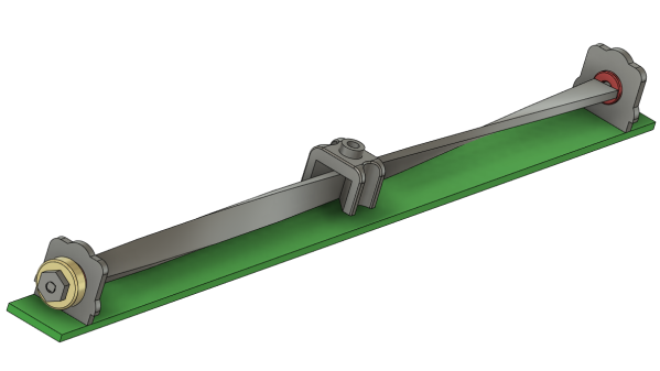
The solution [Nixieguy] settled on was to use a Hall effect sensor and a diametrally magnetized neodymium ring magnet. The magnet is rotated through 180 degrees by a twisted aluminum bar, which is supported in a frame by bearings. A low-friction slider with a slot captures the bar; moving the slider along the length of the control rotates the bar, which rotates the magnet, which allows the Hall sensor to measure the angle of the magnetic field. Genius!

The parts for the prototype sensor are all made from 0.8-mm aluminum sheet stock and bent to shape. The video below shows the action better than words can describe it, and judging by the oscilloscope trace, the output of the sensor is pretty smooth. There’s clearly a long way to go to tighten things up, but the basic mechanism looks like a clear win to us.

Hats off to [Nixieguy] for this one, which we’ll surely be following for more developments. In the meantime, if you need to brush up on the Hall effect, [Al Williams] did a nice piece on that a while back.

Continue reading “Clever Mechanism Makes A Linear Control From A Rotary Hall Sensor”

Using Statistics Instead Of Sensors

Statistics often gets a bad rap in mathematics circles for being less than concrete at best, and being downright misleading at worst. While these sentiments might ring true for things like political polling, it hides the fact that statistical methods can be put to good use in engineering systems with fantastic results. [Mark Smith], for example, has been working on an espresso machine which can make the perfect shot of coffee, and turned to one of the tools in the statistics toolbox in order to solve a problem rather than adding another sensor to his complex coffee-brewing machine.

To make espresso, steam is generated which is then forced through finely ground coffee. [Mark] found that his espresso machine was often pouring too much or too little coffee, and in order to improve his machine’s accuracy in this area he turned to the linear regression parameter R2, also known as the coefficient of determination. By using a machine learning algorithm tuned to this value, which assesses predictable variation in a data set, a computer can more easily tell when the coffee begins pouring out of the portafilter and into the espresso cup based on the pressure and water flow in the machine itself rather than using some other input such as the weight of the cup.

We have seen in the past how seriously [Mark] takes his coffee-making, and this is another step in a series of improvements he has made to his equipment. In this iteration, he has additionally produced a simulation in JupyterLab to better assist him in modeling the system and making even more accurate predictions. It’s quite a bit more effort than adding sensors, but since his espresso machine already included quite a bit of computing power it’s not too big a leap for him to make.

Extreme Espresso, Part 2: An Inductive Water Level Sensor

[Mark Smith] must really, really like his coffee, at least judging by how much effort he’s put into tricking out his espresso machine.

This inductive water tank sensor is part of a series of innovations [Mark] has added to his high-end Rancilio Silvia machine — we assume there are those that would quibble with that characterization, but 800 bucks is a lot to spend for a coffee maker in our books. We recently featured a host of mods he made to the machine as part of the “Espresso Connect” project, which includes a cool Nixie tube bar graph to indicate the water level in the machine. That display is driven by this sensor, the details of which [Mark] has now shared. The sensor straddles the wall of the 1.7-liter water tank, so no penetrations are needed. Inside the tanks is a track that guides a copper and PETG float that’s sealed with food-safe epoxy resin.

Directly adjacent to the float track on the outside of the tank is a long PCB with a couple of long, sinuous traces. These connect to an LX3302A inductive sensor IC, which reads the position of the copper slug inside the float. That simplifies the process greatly; [Mark] goes into great detail about the design and calibration of the sensor board, as well as hooking it into the Raspberry Pi Zero that lies at the heart of “Espresso Connect’. Altogether, the mods make for a precisely measured dose of espresso, as seen in the video below.

We’d say this was maybe a bit far to go for the perfect cup of coffee, but we sure respect the effort. And we think this inductive sensor method has a lot of non-caffeinated applications that probably bear exploration.

Continue reading “Extreme Espresso, Part 2: An Inductive Water Level Sensor”

Flexible Actuators Spring Into Action

Most experiments in flexible robot actuators are based around pneumatics, but [Ayato Kanada] and [Tomoaki Mashimo] has been working on using a coiled spring as the moving component of a linear actuator. Named the flexible ultrasonic motor (FUSM), [Yunosuke Sato] built on top of their work and assembled a pair of FUSM into a closed-loop actuator with motion control in two dimensions.

A single FUSM is pretty interesting by itself, its coiled spring is the only mechanical moving part. An earlier paper published by [Kanada] and [Mashimo] laid out how to push the spring through a hole in a metal block acting as the stator of this motor. Piezoelectric devices attached to that block minutely distorts it in a controlled manner resulting in linear motion of the spring.

For closed-loop feedback, electrical resistance from the free end of the spring to the stator block can be measured and converted to linear distance to within a few millimeters. However, the acting end of the spring might be deformed via stretching or bending, which made calculating its actual position difficult. Accounting for such deformation is a future topic for this group of researchers.

This work was presented at IROS2020 which like many other conferences this year, moved online and became IROS On-Demand. After a no-cost online registration we can watch the 12-minute recorded presentation on this project or any other at the conference. The video includes gems such as an exaggerated animation of stator block deformation to illustrate how a FUSM works, and an example of the position calculation challenge where the intended circular motion actually resulted in an oval.

Speaking of conferences that have moved online, we have our own Hackaday Remoticon coming up soon!

Continue reading “Flexible Actuators Spring Into Action”