The number of satellites whizzing by over our heads at any moment is staggering, and growing at a rapid rate as new constellations are launched. But sometimes it’s the old birds that are the most interesting, as is the case with some obsolete but still functional military communications satellites, which thanks to a lack of forethought are largely unsecured and easily exploitable. And all that’s needed to snoop in on them is a cheap ham radio and something like this simple and portable satcom antenna.
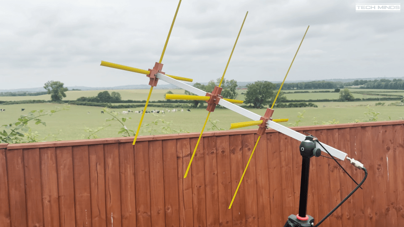
As proof of the global nature of the radio hobby, the design in the video below by Brit [Tech Minds] borrows heavily from previous work by Italian ham [Ivo Brugnera (I6IBE)], which itself was adapted to use 3D-printed parts in a German blog post a few years ago. The common thread is the use of tape measures for the elements of the aptly named turnstile antenna, a tried and true material for lightweight, foldable antennas that amateur radio enthusiasts have been using for years. The antenna is similar in design to the classic three-element Yagi-Uda, with a crossed pair of driven elements in the middle of a boom that also supports a reflector and a director. Strips of tape measure material are held to the 20-mm aluminum tubing boom with 3D-printed brackets. A phasing harness of precisely cut coax cable connects to the driven elements and runs down the boom; the quarter-wavelength loop serves to introduce the 90° phase shift needed for the circularly polarized signal from the satellites.
A quick scan with a vector antenna analyzer showed just how well this antenna performs on the 220-MHz band, and the antenna was easily able to pick up the Brazilian satellite pirate’s chatter. The tape measure elements make the antenna easy to handle and foldable, not to mention pretty cheap to build. And what’s not to love about that?


Sounds more like distress call from People who try to escape Lybia and other collapsed states around South-Europe / North-Asia region.
These audio are basic truckers
The skin depth of tape measure steel at VHF frequencies is just 2.8 microns. Most of the RF current is limited to that thickness of quite resistive metal. It’s a horrible conductor for RF energy, and acts more like a dummy load. It has 50 (!) times the loss of an equivalent copper element.
It helps (a lot) that the tape measure has a relatively large surface area, but you’ll be better off using aluminum tubing for the elements.
If tape measure is very lossy for this freq, it will be revealed when the gain is measured, right? I am trying to point out the importance of measurement, including a test of the balun’s ability to prevent shield current.
Yes, it will show up in you gain measurement. As for Paul’s comment, I am curious how much loss on equivalent copper element has to begin with. The 50x loss number seems to be in the right ballpark (obviously it depends on the steel used), but I am too lazy to simulate such a dipole to determine how much gain you are really loosing. Generally dipoles are very efficient, so a dramatic increase in loss resistance may still leave you with a usable antenna.
The stainless steel elements will reduce the gain a bit, but not by a huge amount. I though that this was a pretty interesting question so to quantify it, I simulated the antenna in HFSS. I ran two simulations. One with the elements as pure copper and the other with stainless steel elements. The boom was aluminum in both sims. I used a 0 and 90 degree feed directly on the driven elements. The peak gain profile over frequency was pretty similar with the copper vs stainless steel. The peak gain of the antenna was at 234 MHz with a peak RHCP gain of 9.2 dBic with copper elements and 8.75 dBic with stainless elements. So about a 0.5 dB drop. This was the maximum delta between the two metal antennas with there being less of a gain drop at other frequencies. Note that I design antennas for satcomm.
Thank you for running the simulations! I also recall that several cubesats have successfully flown deployable antennas made from lengths of tape measure. They just use fishing line and a resistive heater for the hold-down and release mechanism.
I’m curious, have you ever compared brass rod to copper and/or aluminum tubing?
I don’t believe that is a dipole. I am pretty sure it is a beam.
indeed.
there is however an alternative that is far better; aluminium venetian blind.
+1 for recycling concept!!
Thanks for the idea
Typical “new” hamsters. Crapping on the cheap easy way to get into the hobby. Let my expert ticket with code expire years ago. I operate on any frequency I want,when I want, and no one can stop me. The true operators died off and now we have these wannabes. So sad.
Sounds like a crossed yagi, not a turnstile, despite the similarities in appearance and phasing harness. The directors and reflectors turn it from an omnidirectional horizontally polarized antenna to a beam antenna.
Wouldn’t it have more gain if more directors were used? Asking for a friend.
Rather than soldering on tabs couldn’t one just cut the elements a little long then trim the width of the extra length and sand off it’s paint to make tabs?