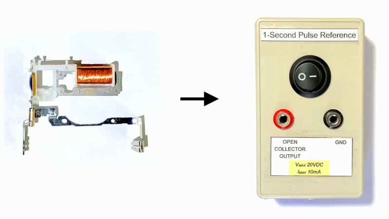
If you’re looking for a 1-second time reference, you’d probably just grab a GPS module off the shelf and use the 1PPS output. As demonstrated by [InazumaDenki], though, an old quartz clock module can also do the job with just a little work.
The module was harvested from an old Seiko wall clock, and features the familiar 32.768 KHz crystal you’d expect. This frequency readily divides down by 2 multiple times until you get a useful 1 Hz output. The module, originally designed to run a clock movement, can be repurposed with some basic analog electronics to output a useful time reference. [InazumaDenki] explains various ways this can be done, before demonstrating his favored method by building the device and demonstrating it with a decade counter.
It has some benefits over a GPS time reference, such as running at a much lower voltage and needing no external signal inputs. However, it’s also not going to be quite as accurate. Whether that matters to you or not depends on your specific application. Video after the break.


Funny. I did exactly the same thing a few years ago, to get a stable 1 PPS independent of GPS.
Issues:
– The even and odd pulses are each not exactly 1s. They are about 50 us different on mine. Not a huge issue: they average out.
– There is some dependence of rate on supply voltage. Use a regulated supply.
– Even with a regulated supply I noted an issue with ground loops and loading. I now use an isolated supply.
– There is some dependence of rate on temperature. Mine is in a 40 C oven.
True rate is obviously not exactly correct. In principle you can discipline this by replacing the crystal’s capacitor with a varicap, and adjusting the tuning voltage, to lock to (e.g.) GPS. I didn’t bother. Instead of building and fiddling with a PLL that would take an age to tune, I let it free run and just keep track of the rate relative to other sources. One of these days I’ll get a proper Allan variance plot of it.
Ah the work we put into being on time for our appointments.
I did a similar build years back and purchased 10x clock modules from eBay. After successfully working through the build for an Arduino clock, I found a far better approach from Alex:
https://www.insidegadgets.com/2011/10/08/how-to-use-a-32khz-watch-crystal-on-an-attiny85/
Sorry this is nowhere near a clock reference and also completely trivial. Any 5ppm 32. 768 kHz crystal for 1$ and a 16 bit counter ic will propably perform a lot better.
Funny I just took apart a dead steam punk style round case clock for the case. I noticed the little plastic pin on the motor gear had sheared off. When I put a cell in it ticked back and forth between the 2 poles, a short pulse on mostly off. The magnetic path is different than the one in the picture. I suspect that your clock uses a 4 pole even (nearly) on off as a 2 phase?
Anyway there are at least 2 versions of this little blob and a crystal driving a motor to run a clock dial.
I’ve seen prior references on Hackaday to using GPS modules for their 1 Hz output. For anyone looking for other options, there are also various low-cost Real Time Clock (RTC) modules that can provide the 1 Hz pulse to a circuit. If used with a microcontroller it can provide all hh:mm:ss functions as well as date, month, year, leap year, etc., without needing any reception of an external signal. I use modules based on the DS1307 (because I have several), but there are many out there.
Yeah, this is a fun project but I’m really struggling to imagine any case where this is gonna be better than a $1 aliexpress RTC module. Maybe as a novelty in an analog circuit where you don’t wanna use a crystal and a counter for whatever reason.
FYI – ‘Real Time Clock’ is a marketing term, not a technical one. It means nothing more than ‘output in hh:mm:ss format’ and implies nothing about accuracy or stability. For timekeeping purposes, stability is the most important spec.
For reference, the DS1307 is stable to about 30ppm, meaning up to 2.5s of drift per day is within spec, independent of external factors like temperature or variations in supply power.
More advanced chips like the DS3231 have internal temperature compensation and are spec’d to 2ppm. Drift of maybe 1 second per week, or 1 minute per year is within spec. The fact that the chip does have temperature compensation means the DS3231 is about 10x less sensitive to temperature changes than the DS1307.
The GPS system is synced to the atomic clock system, which is stable to about 1.4 parts in 1e18.. roughly 1 second of drift in 20 billion years. The PPS signal from a GPS module is typically spec’d to +/-10ns of jitter relative to the GPS clock system, and is basically immune to drift. The gap between any two pulses is an integer number of seconds to within +/-20ns worst case, or +/-14ns statistically.
The long term, non-drifting nature of the GPS PPS system makes it an excellent tool to identify and correct drift in other clock systems.
Hi Mike, very interesting post. I’m new to this blog but I’d like to pick your brains if I may. I’m an electronics engineer, officially retired but still active. I’m also very much an analogue engineer so I don’t do programming and know as good as nothing about it.
A while back I designed/built a master clock generator to run our four wall clocks in the house. Simple, just the standard arrangement with the crystal, dividers and bi-polar 0.5Hz line driver, this with LiPo batteries as we have frequent power outages here in South Africa.
But I’m looking for something more accurate than the conventional clock generator and I’m interested in using the DS3231 you mention, haven’t come across it before. I can get the MZ suffix version quite cheaply but it’s only 5ppm accuracy, which, I suppose, should be adequate. The S version is substantially more costly at around $12 from our local Mouser. Lots of Chinese knock-offs but I’m not so sure about their accuracy.
Can you advise me, please? My plan is to put the 1Hz O/P through a divide by 2 chip and use it that way as I have at the moment with a 4000 series oscillator. I was using the 50Hz mains divided down, but we are subject to much load shedding and the 50Hz is anything BUT 50Hz, hopeless.
You also mentioned using a GPS. Can you advise me about that, too, please? AliExpress has modules but I don’t know how to implement them without fancy software.
If you’d prefer, and if you wouldn’t mind, you can reply direct to me at burischroland@gmail.com. I would be most appreciative.
Thanks and best,
Roland.
https://www.amazon.co.uk/dp/B095GLPZ9N?ref_=pe_3052080_397514860
Most GPS modules are configured to start to emit PPS signal as soon as the get the lock. Just Look for modules with PPS signal, attach antenna, place it somewhere where it sees the sky (north sky is preferable if you are south of the Equator), apply the power and wait for PPS diode to start blinking. At that moment PPS signal should be alive too.
Most modules allow you to configure them using some configuration application. You just need USB to TTL serial converter and application for specific module. If you are unsure which type of GPS to buy just try some modules from uBlox, but be beware there is a lot of knockoffs and direct fakes on the market.
Warning: Most of the “analog clocks” I’ve encountered these days are pseudo-digital but they have a sweep second hand like a true-ish analog movement. These sweep second hand digital clocks are really electromechanical (Lavet-Type [1]) movements that are pulsed with a ~8Hz in-phase bipolar signal across the electromagnet to make the second hand appear to sweep smoothly. Today it is getting harder to find a quarttz pseudo-analog clock movement that actually ticks (pulses) once per second.
1.Lavet-type stepping motor
https://en.wikipedia.org/wiki/Lavet-type_stepping_motor