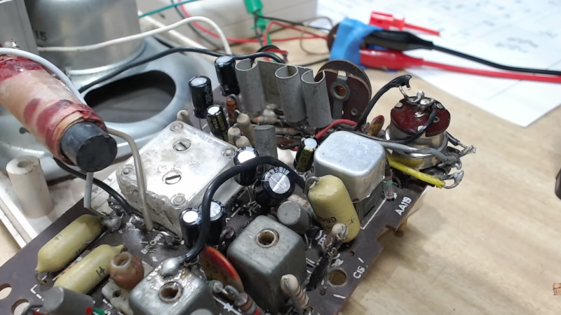
The humble transistor radio is one of those consumer devices that stubbornly refuses to go away, but it’s fair to say that it’s not the mover and shaker in the world of electronics it might once have been. Thus it’s also not a staple of the repair bench anymore, where fixing a pocket radio might have been all in a day’s work decades ago now they’re a rare sight. [David Tipton] has a Philips radio from we’re guessing the later half of the 1960s which didn’t work, and we’re along for the ride as he takes us through its repair.
It’s an extremely conventional design of the era, with a self-oscillating mixer, 455 kHz IF amplifier, and class AB audio amplifier. The devices are a little archaic by today’s standards, with comically low-gain germanium transistors and passives from the Ark. Injecting a signal reveals that the various stages all work, but that mixer isn’t oscillating. A lot of fault-finding ensues, and perhaps with a little bit of embarrassment, he eventually discovers a blob of solder shorting a collector resistor to ground. All isn’t over though, for the volume pot is also kaput. Who knew that the track from a modern component could be transplanted into one from the 1960s?


A ceramic capacitor is unlikely to be “leaky”, and even those resistors usually don’t have problems. I would have focused right away on the autodyne, which is the most common source of problems in these receivers.
Yes, but nobody aged below sixty knows. ;-)
Yeah, if you can’t buy it from eBay and doesn’t plug into breadboard with accompanying diagrams…
The difference is that us ‘oldies’ had to know the subject well and be far more creative to build or repair anything, particularly without internet.
Germaniums were the source of much early learning and fun, supporting crystal sets formed around toilet rolls, to scratching the paint off an OC71 for light-sensitive projects 😄
Are we gonna berate kids these days for not knowing much about steam engines or ploughing with horses too?
Yes it’s important to preserve knowledge and skills but we can’t expect everyone to learn arcane technology just because we learnt it. For most purposes those modules from ebay are by far the cheapest quickest and most reliable way to _get things done_, so unless you want the exercise of building it from scratch there’s no point going the long way round.
Not at all John, but the days when there was no choice but to learn and ingest working principles to design and get anything working are long-gone, yet principles are timeless.
I train and mentor new engineers and interns for a global semiconductor manufacturer, and without exception, they extoll how much they’ve learned and how empowering it is to grasp fundamental working principles to design and debug, rather than copy-paste from published datasheets and app notes. Much of this is lost on the ‘plug & play’ culture, where it is no longer necessary to question ‘how’ or ‘why’.
One of my favourite interview questions is to ask the interviewee to describe the positive feedback mechanism of a simple classic crystal clock oscillator formed around an inverting gate. Staggering how even seasoned professionals have absolutely no idea.
The DIY radio world died in early 80s with the TDA7000.
All these old techs will be gone soon, can’t get young people interested in being radio techs, the world is doomed in respect to high level repairs
Just someone likely said 100 years ago “Soon, no-one will know how to plow a field with a mule”…
Autodyne?? what do you mean?
Autodyne sounds like it’s related to heterodyne or superheterodyne, which AFAIK is the principle all modern radio receivers (including cell phones, television sets) use. A quikipedia search….
Exactly, autodyne is a circuit that combine the HF amplifier, the local oscillator and the mixer by using a single transistor (or tube): it was very common back then when transistors were very expensive.
I knew exactly what you meant, but I’ve never heard it called that. Weren’t autodynes used in early valve days as detectors (dredging the furthest reaches of my memory)
Dear Paul: according to the schema the detector is D2, right after the second stage IF transformer.
I have found that old stuff that was made by human hands in the 60s and 70s often has solder joints that go bad. When you can’t get something to work, try refreshing solder joints.
I worked in electronics repair and maintenance in both professional environments (TV studios) and domestic repair shops, in the ’80s and ’90s. Biggest secret of that work was that most repairs were bad solder joints. Mostly caused by heat expansion/contraction.
It’s worse these days with low quality lead-free solder and ‘safer’ flux. Not only do we see more dry joints, we see tin whiskers as well!
Yes, I’ve had direct experience of tin whiskers from tested items put into stock, removed for end-user customisation a year later, and nothing worked. Also recalling how medical, military, and aviation had special dispensation after RoHS legislation, though probably as much to do with type-approvals and compliant processes.
I believe tin whiskers was something to do with a stress mechanism after higher-temperature post-reflow cooling, though rarely encountered nowadays… AFAIK.
I recall feeling very relieved on hearing of the exemptions. I didn’t fancy the idea of whiskers forming in a 2MT nuke! Nor in a pacemaker, come to think of it.
Tin whiskers are making a comeback with lead free solder. It is the perfect mix for whisker growth.
GE commercial radios were known for it, (open the helical cans, run your lighter over them and they work again) lose of recieve was common.
Excerpt from a long article from a dead link which, luckily, I printed to PDF.
Questioning some current dogmas is verboten.
Was Lead-Free Solder Worth the Effort?
by Jon Titus, Senior Technical Editor
12/28/2011
The ban on lead in electronic solder caused the most controversy because as far as I can tell, no research showed environmentally significant amounts of lead leaching from discarded electronic equipment into groundwater in Europe, Canada, or the US. Granted, disposal and salvage techniques in third-world countries, where such studies are unlikely to occur, probably causes local pollution of water, soil, and atmosphere. Much of the push to eliminate lead from solder, though, stemmed from the public perception of hazardous wastes as portrayed in the news stories I mentioned above. In Europe, the “Greens” played upon environmental fears, pushed legislators to eliminate lead, and dismissed the need for a scientific understanding of heavy-metal pollution (if any). As best as I can remember, consumers didn’t clamor for lead-free solder and little or no evidence surfaced to show lead contamination in potable water.
I guess the lead-acid automotive batteries mean a magnitude higher lead contamination than discarded PCBs.
And don’t forget the germanium transistors itselfs … at least certain types can have internal shortcuts:
https://nepp.nasa.gov/whisker/anecdote/af114-transistor/index.html
Thanks a million. Great material.
Yes indeed!
Resistors and ceramic capacitors rarely fail. They can fail if exposed to excessive voltage or current, or if they are physically damaged, but none of those things is likely to happen inside a transistor radio. Electrolytic capacitors are another matter; they are likely to need to be replaced if the radio contains any. Inductors don’t fail outright, but their values can drift and cause the radio to go out of alignment.
Aside from mechanical issues if the radio has a tuning arrangement that’s more complicated than a knob that’s directly connected to a polyvaricon capacitor (a type of variable capacitor that’s common in those radios; it has metal plates that are separated by thin plastic sheets), the most likely failure points are electrolytics (already mentioned) and the transistors. Germanium transistors are no longer made, so if you have to replace them you’ll have to find some new old stock or salvage them from other similar radios. If you have a slightly newer radio with silicon transistors, modern replacements should work.
Comset Semiconductor in Belgium has germanium transistors in current production. NTE also appears to make germanium transistors.
It’s nice to know that Comset is still making them.
So far as I know, NTE doesn’t make anything. They sell replacement semiconductors (transistor and ICs) that are made for them by various manufacturers and labeled with NTE part numbers. Whatever germanium transistors they have are either made for them by somebody (perhaps Comset) or are parts that they bought back when major semiconductor companies were still making them. Demand is low and NTE parts usually aren’t cheap so their stock can last a while.
NTE currently offers the NTE102, which they list as a suitable replacment for the CK722, one of the more popular germanium transistors. It costs $6.96 from their direct sales division in quantity one; distributor prices are similar. At those prices, repairing most devices that use germanium transistors is not cost-effective, especially if you need to replace more than one.
CK722 sold for a whopping $7.60 (equivalent to $87 today) when introduced in 1953. In early 60s transistors were still a novelty here in Italy at a price roughly equivalent of a couple of pizzas each.
Recently I needed a NTE6401 for a repair ad it did cost me nearly 10€ O_o
resistors fail at the same rate that lytics do. have you not seen them that have a bubbly appearance, or have drifted 50% out of value? Most 1940s radios need a wholesale resistor as well as a wholesale recap
I have seen resistors fail like that… in tube devices, where they are subjected to heat and high current. Resistors in transistor radios aren’t stressed that way so they rarely fail.
A solder blob sounds like a manufacturing defect unless it was a bad way of describing a cold joint. I did audio equipment repair for many years before moving into industrial electronics, and working on stuff right off the line. It was new to me because the stuff I was used to working on HAD worked at one point in time so it was some kind of a failure. At the new gig there was a lot of manufacturing defects from solder blobs across pins to the wrong parts in the wrong holes to parts in backwards. We had one thing that if the assemblers did something backwards, a big electrolytic would go bang, we used to call that test jug the fire tester. Anyway, on this radio if it was a short blob, it sounds like this radio never should have worked..
I thought it meant that the solder blob was the result of a rework attempt by [David Tipton], and he later found it and discovered is was a source of a problem.
those beige capacitors are the best in the world. 60 years old and still going strong. in all my years of repairing, i only once came across a broken one. due to mechanical stress, it had developed a small crack. I even go so far as to salvage them from old chassis for reuse.
Nice. But not a hack at all.
nobody cares.
Rebuilding the volume pot using parts of a modern pot meets my criteria for a hack.
+1
Little sales history about cheap transistor 9V radios. The transistor radio was a very clone copied design. The basic design let’s say it used 8 transistors (so long ago I forget). The sales guy said put another transistor in, I will sell it as a 9 transistor radio. The engineer said it’s not going to do any better. Sales said don’t care. So the engineer put in another transistor which sat in the corner of the PCB connected to nothing. OR so to say a repair spare.
To increase the transistor count, oftentimes engineers would use the emitter-base junction of an extra transistor in place of a germanium diode. It worked.
The power of marketing: https://upload.forumfree.net/i/ff12198759/IMG_20210108_172448.jpg
6 transistors, look at TR3 :-)
https://upload.forumfree.net/i/ff11952375/SWOPS_Six_Transistor_0.png
Having made my living some sixty years ago repairing these radios, I can tell you an oscilloscope is your best friend. Start signal tracing at the wiper of the volume control and go from there. Signal presence, amplitude, frequency and DC or AC voltage levels are all right there on the scope. For AM radios, even the cheapest of scopes will suffice. Component tolerances are as wide as a barn door. Very early radios even had the base bias set for each stage with potiometers! Transistors varied so widely even when they had the same part number. Most often failure was electrolytic caps. Low voltage, high value caps in the day were and still are problematic. For quick troubleshooting, I still prefer a scope!
+1 thanks for insightful comment.
The era of the superhet receiver wasn’t exactly causing the smartest design decisions.
The ever increasing number of transistors and superhet stages (double super, tripple super etc) had a price – self-noise of the transistors harmed sensitivity.
At some point, the noise of the transistors was stronger than a weak RF signal.
Unfortunately, it seems, the people in charge either were too blind to see or didn’t care.
Other, simpler receiver designs, like the audion, the direct-conversion receivet (dc receiver), the crystal radio (!) and the regenerative receiver were cleaner in demodulation than the average pocket radio of the day.
Agree. Simply sensitivity was no more an issue due to increasing number of repeaters, more transmitting power, etc. Instead selectivity became a major problem with more and more stations on near frequencies.
For DX there’s nothing better than super-regen.
This isn’t entirely true. Multiple conversion designs were not just driven by a desire for complexity. They also existed because they could deliver features that were difficult or impossible to get in other ways.
For example, look at the Kenwood TS-930 and TS-940, which were a triumph in their use of multiple conversion. On sideband, the receiver presented you with two knobs; one adjusted the low frequency cutoff of the filter, the other adjusted the high frequency cutoff. On CW they took on different roles: one adjusted the center frequency and the other adjusted the filter bandwidth.
Nowadays we’d do that kind of thing with DSP, and some radios do. But the Kenwoods did it with no DSP and no variable bandwidth filters! It was all done using triple conversion with high quality SSB bandwidth crystal filters at the second and third IF (the first IF was up-conversion and had a wider roofing filter) and simultaneous tuning of multiple local oscillators: the main tuning that handled conversion from the input frequency to the first IF, the one for conversion from the first to second IF, and the one for conversion from the second to third IF. The radio was adjusting the position of the signal within the passband of all of those filters simultaneously to make those knobs do what they did, and it was all seamless from the operator’s point of view; the controls just did what they claimed to do, even though a lot was going on behind the scenes.
Those particular rigs were not champions of dynamic range, though they were competitive with their contemporaries. Receivers with more than 100 dB of dynamic range came later, and it has been achieved in a number of ways. Some years back I looked at the top 10 rigs in the Sherwood ratings, and there were four different types of receiver there: single conversion superhet (plus a second conversion to a low IF for DSP filtering), a triple conversion superhet (which also had DSP at the third IF), an SDR using a quadrature sampling detector, and an SDR using DDC (direct downconversion using an ADC that samples at over 100 MHz). All four were able to achieve more than 100 dB of two-tone dynamic range and an MDS (minimum discernable signal, a measure of sensitivity) of -130 dBm or better. Now you have to look at the top 15 to see all four types represented, as more DDC designs have shown up at the top.
A summary of the top 15 radios (included two K3S samples):
Yaesu FTdx-101D/MP: direct sampling
FlexRadio 6700: direct sampling
Yaesu FTdx10: direct sampling
Yaesu FT-710: direct sampling
Icom IC-R8600: direct sampling up to 30 MHz, double conversion to 1100 MHz, triple conversion to 3 GHz
Elecraft K3S: “one and a half conversion”: second IF is a near-zero IF for DSP
Elecraft K3 with upgraded synthesizer: one and a half conversion
Icom IC-7851: triple conversion
Kenwood TS-890S: single conversion with direct sampling at first IF (8.248 MHz)
Hilberling PT-8000A: multiple conversion (at least two)
Elecraft KX3: quadrature sampling
Apache ANAN-7000DLE: direct sampling
Elecraft K4D: direct sampling (optional one and a half conversion second receiver)
Yaesu FTdx-5000D: triple conversion
Although it seems dificult but in seventies we used to repair it a lot with only the help og multimeter only …there are three stages first is amp second is Rf and third is oscillation…very easy.
Haha. I don’t get the title even without reading the article. Why would anyone assume that a superhet receiver circuit with maybe a hundred parts and twice that number of connections would be simple to diagnose. With respect to a modern soc board where 95% of fixes are replacing the chip, yes, it is quite a procedure.