Last time, we’ve used a logic analyzer to investigate the ID_SD and ID_SC pins on a Raspberry Pi, which turned out to be regular I2C, and then we hacked hotplug into the Raspberry Pi camera code with an external MCU. Such an exercise makes logic analyzers look easy, and that’s because they are! If you have a logic analyzer, you’ll find that a whole bunch of hacks become available to you.
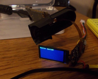
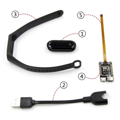 In this article, let’s figure out places where you can use a logic analyzer, and places where you can’t. We’ll start with the first limitation of logic analyzers – capture speed. For instance, here’s a cool thing you can buy on Aliexpress – a wristband from TTGO that looks like a usual fitness tracker, but has an ESP32 in it, together with an IMU, an RTC, and an IPS screen! The seller also has an FFC-connectable devboard for programming this wristband over UART, plus vibromotor and heartrate sensor expansion modules.
You can run C, MicroPython, Rust, JavaScript, or whatever else – just remember to bring your own power saving, because the battery is super small. I intended to run MicroPython on it, however, and have stumbled upon a problem – the ST7735-controller display just wouldn’t work with the st7735.py library I found; my image would be misaligned and inverted.
The specifications didn’t provide much other than “ST7735, 80×160”. Recap – the original code uses an Arduino (C++) ST7735 library and works well, and we have a MicroPython ST7735 library that doesn’t. In addition to that, I was having trouble getting a generic Arduino ST7735 library to work, too. Usually, such a problem is caused by the initialization commands being slightly different, and the reason for that is simple – ST7735 is just the name of the controller IC used on the LCD panel.
Each display in existence has specifics that go beyond the controller – the pixels of the panel could be wired up to the controller in a bunch of different ways, with varying offsets and connection types, and the panel might need different LCD charge pump requirements – say, depending on the panel’s properties, you might need to write 0x10 into a certain register of the ST7735, or you will need 0x40. Get one or more of these registers wrong, and you’ll end up with a misaligned image on your display at best, or no output at worst.
2 Fast 2 Catch
 First, I tried reading the code to compare the initialization parameters by sight. However, it was abstracted enough to be hard to compare – the C++ code looked something like
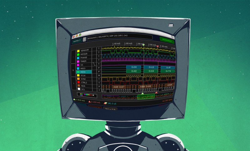
 write_to_display(ST7735_PWCTR1 , 2+TFT_INIT_DELAY, 0x02, 0x70, 10) and the MicroPython code looked like write_to_display(0xC0, 0x80, 0x02, 0x70, 0xA). Decoding sixty lines of #define-heavy C code was not in my plans for the day, and I wired up my logic analyzer to the display’s SPI pins, aiming to capture the commands as they’re transferred.
The display has a bunch of pins we can see on the wristband schematic. One of them is SPI data in, another is SPI clock, and one more is called RS, also known as D/C or A0 on other SPI displays like this – it’s used to let display know whether you’re sending commands or data (pixel values). There’s also RESET and CS pins, but we don’t need to capture them – we have no other devices on this SPI bus so CS is meaningless, and we don’t care when the display is reset, either. As a result, we only need to wire up three GPIOs to our analyzer.
 However, if you run the logic analyzer in this state, you will notice a problem fast – the signal doesn’t make much sense, the clock is garbled and the packet data won’t decode. Here’s where our $5 logic analyzer fails – we need to capture a whole bunch of SPI data, but the SPI speed used by this code is simply way too fast. It makes sense – you want to transmit data to your display as quickly as you can, so that your images appear on it quicker.
This is a limitation of USB 2.0 interface that the FX2 chip inside our analyzer can use; our logic analyzer has 480 Mbps connection speed, and that’s 480 megabits per second which is only 60 megabytes per second, and that’s without USB protocol and logic analyzer low-level protocol overhead. These analyzers are referred to as 24 MHz analyzers for a reason – that’s about the fastest frequency you can stream bytes to your PC, and our SPI interface was set faster than that, because it made sense to do so. And, again, you want to use a capture frequency that’s three or four times higher than the signal frequency – capturing at twice the frequency is theoretically okay, but in practice, it will result in missed datapoints, as the signals we’re measuring are imperfect.
Slow Down To Compare
There are three ways you can work around such a problem. The first is getting a faster logic analyzer – there are analyzers that connect through a USB3 port, and you can buy them online. There are also logic analyzers that have a memory chip on them – they capture a higher-speed signal for a certain amount of time into their memory chip, and then transmit all the captured data to your PC through the comparably slower USB interface. This is not as convenient as the streaming mode we get with FX2 analyzers, but it does make certain kinds of captures possible! And, if you were wondering, our FX2 analyzers don’t have extra memory in them for such a trick.
The third way, as you might have guessed, is to lower the SPI speed in the code! Displays are typically fine with a low SPI speed – it’s far more common to see “highest possible” speed limitations than “lowest possible” ones. On the MicroPython side, that was trivial, and on the factory firmware side, it took a bit of time to find the source code for it – the official GitHub only seemed to have .bin files at first, I had to dig in the “Examples” folder to actually find the source code for those.
 After capturing the display communications, I could export logs of both of the communications, and see which initialization parameters the Arduino library actually uses. Then, I put the working SPI initialization parameters into the MicroPython ST7735 library source code, and the MicroPython-driven display started to work properly!
Low capture speed will not be an issue for low speed interfaces like UART, I2C, and many others – which is why I started the first article with I2C as an example, as it’s hard to screw that up. For interfaces like SPI, speed can be a problem.
For instance, grab your nearest ESP32 or ESP8266 devboard – it will have a qSPI (quad SPI) interface to talk to the flash chip, and this interface is typically exposed on SD0-3 pins on cheap devboards; unwisely so, as wiring up to those pins can only really break things unless you know what you’re doing. This interface typically goes at 40 MHz or even higher, which does require you to get a decently specced analyzer as 25 MHz max will no longer do, and you can’t just lower the interface speed either.
Speed isn’t the only limitation for logic analysis, either – not all interfaces can be easily tapped to begin with.
Bring Extra Hardware
A logic analyzer can only capture digital, logic-level signals referenced to ground, swinging from ground to 3.3 V or 5 V. We know these as single-ended signals, and these include SPI, I2C, UART, and many others. However, in this intricate tech world, many signals are differential, many are analog, and some are digital but have an analog component to them.
Let’s take RS232, RS485 and CAN – they’re powerful interfaces used in automotive and embedded settings; your car likely has a CAN network in it, and if you’re working with some industrial equipment, it might have a RS232 or RS485 connection exposed for communication purposes. However, RS232 is decidedly not logic level – instead of 0 V and 5 V, it goes from -12 V to 12 V. RS485 and CAN, on the other hand, are differential interfaces – if you don’t recall, a differential pair encodes 0 and 1 with two signals, and the voltage levels on those pairs are relative to each other as opposed to ground – not logic-level signalling at all.
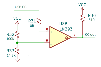 Not all is lost, however – all you need to do is to get a RS232/RS485/CAN to logic level PHY chip, set it to receive mode, and listen in on the output of it – receiving all the bus communications, nicely converted to a logic level range! Same goes for the USB-PD communications, except I haven’t quite seen a PHY that lets you receive the PD comms as a logic level signal – however, you can make a circuit with an operational amplifier and listen in on the deepest secrets of your USB-C devices.
A similar situation is with the USB interface – you might remember that some USB devices run at 12 Mbps, which is a relatively low speed; such devices are mice, keyboards, and many MCUs like the RP2040. You might think that it’d be easy to wire up such a USB signal to a logic analyzer, but not so fast – USB uses a differential pair too! Worse, the pair is also half-duplex – you can transfer data from host to device, or from device to host, but not both at the same time.
So, if you wanted to capture USB communications, you’d need to tap into D+ and D- wires, convert them into a single-ended signal somehow, let’s say, with an operational amplifier that’s fast enough, and then interpret the USB packets’ direction from their contents. Mind you, this would only cover 12 Mbps (Full-Speed) communication – USB works a bit differently at 480 Mbps (High-Speed), and it would be out of range of a cheap analyzer anyway. This is why dedicated logic analyzers exist – they might have a somewhat hefty price tag, but they can be indispensable. There’s also software USB packet capture options that you can use, for instance, Wireshark has a plugin for that.
Out Of Range
Of course, there’s a whole bunch of interfaces that are even faster than that. If you want to analyze PCIe, USB3, or DisplayPort, you’ll want to get a dedicated analyzer instead of a generic one – these interfaces are both differential and seriously fast, and that’s the point where you want to get something purpose-built. A logic analyzer is not as efficient as a dedicated peripheral that receives the signal, it’s an analysis tool first and foremost, and it would do badly sampling a seriously high speed signal when what you really care about are either the packet contents, or the signal’s analog properties.
Even under 100 MHz, things will stay tricky. There’s the LPC interface, which is basically the oldtimey ISA but scaled down to six wires – running at speeds from 33 MHz to 100 MHz. Even though it’s logic level, the LPC signal is a constant stream of messages between the CPU or the chipset and the other peripherals, and it’s not the kind of signal you want to put on prototyping wires without at least buffering it – reflections will get you. In the end, getting an FPGA to decode LPC signals might be way cheaper than getting an analyzer and a hardware setup that could handle straight up LPC decoding. On the upside, if you do get your hands on the LPC bus messages, you get a chance at showing everyone that all those fancy TPMs are not what they seem to be!
Last but not least, here’s one more actionable warning for the road. If you want to capture a 1.8 V signal, your logic analyzer might flake on you – it’d depend on whether it has an input buffer or not, and what kind of buffer that is. With 1.8 V tech getting more and more abundant every day, if you don’t get a signal while probing a piece of tech, you could do good throwing a scope on the pin to double check, and use a logic IC to buffer the signal if it turns out there is indeed activity and it’s just out of input range for your $5 LA!


In case you didn’t figure it out, for the screen orientation you need the highest three bits of the MADCTL register (0x36), which is well documented in the ST7735 datasheet, and for the offset you just need to offset your coordinates when doing the block writes. Both are the result of how different physical LCD panels are wired to the COG chip that controls them. You might also switch between RGB and BGR, also in the MADCTL register, if the colors are wrong.
It seems like a better approach would have been to update the micropython library to use the correct calculation (you could have basically copy-pasted the constants over from the working arduino library) which would both allow you to tweak the display parameters in the future, and potentially help others get the python library working on other devices. Surely that would have been easier than trying to recompile the stock software to slow down the bus…
Speaking of, with I2C you are allowed to manually slow down the bus as a slave by holding the clock line low aka ‘clock stretching’. Some masters have a buggy i2c implementation so it doesn’t always work, but it can be an invaluable tool for slowing things down when dealing with fast i2c busses.
Slowing down communications as done with the ST7735 is a common technique, but once you have the sourcecode, does capturing the data with a LA really save you much from analyzing the source doe itself? And instead of only slowing it down. You can also plugin some redirection in a low lever I/O routine to duplicate the data to somewhere else. But the most offensive I find the short remark about “we don’t need the CS wire”. Normally data is latched into the slave by a low to high transition on the ~CS and without this it simply does not work. ~CS also (re) synchronizes on bytes. But I guess, that if you have a working communication, then omitting the ~CS for your LA still gives you a decent chance to capture the bytes if you manage to keep it in sync.
And as for USB. I have successfully captured low-speed USB (1.5Mbps) with Sigrok and a EUR7 LA. Most of the signalling is indeed differential, but not all of it. There are some bits that explicitly break this rule to set special conditions such as start of packet. It’s a bit like I2C in this regard. My knowledge of USB is close to zero, but with the built-in USB protocol decoder in Sigrok I managed to see an astounding amount of information. Keep alive packets, checksums, special conditions all neatly decoded from the serial stream. It was just a test for me to see if it worked, and I did not pursue it further.
And as a followup posted in the previous LA article:
My Kingst LA2016 has arrived, and it’s original software works on my Linux (Mint 20.3) box. I have not yet used it with Sigrok unfortunately because the download of the nightlies is currently broken on the Sigrok site. I have compiled Sigrok / Pulseview myself some years ago, but it was a nuisance, because I had to get about 5 or 6 separate repositories, and update and compile them one by one.
The “differential” in USB FS/LS is somewhat special, as the J/K states are just one line high (3V3), one line low (0V), i.e. you can read both separately referenced to ground, and do the differential decoding in software. USB FS is often decodable even with 25MS/s, though 40…50MS/s works better obviously.
Sigrok also supports the Salea16 (non-Pro) clones with an FPGA. These let you sample an arbitrary number of channels (i.e. 1 to 16), and only transmits the data of the active channels, thus you can sample e.g. 3 channels at 100MS/s.
Another nice option is Kingst logic analyzers, which use the FPGA to RLE-compress the data into internal memory before sending it to PC. On the top-end LA5032, this allows around 100M signal transitions at 32 channels, even though the bus is the same old USB2. Works well with sigrok.
The Openbench Logic Sniffer is still unbeatable in that space: $50 instead of the $138 of what seems to be the comparable Kingst model. The only problem is it seems to be unobtanium these days, which admittedly is a rather large issue. Still, at 200MSPS on 16 channels it’s not much it can’t do, within reason, as long as you already have one…
If you are looking at define-heavy code, a decent ide will decode and show the result for you on mouse over.
Decent here being pretty much anything but the Arduino IDE, for example VS code.
yep, this whole thing would have been done in a minute or so looking at the code..
Even better, just add printf to the writeReg functions and run the driver as usual.
UK – I saw this artical today, by chance I was in Pound Land this afternoon and saw a ‘VIDO Fitness Tracker’ which is the same as the device shown above. Snapped it up for £13!!
Should be ThirteenPoundLand then.