
Today, I’d like to highlight a tool that brings your hacking skills to a whole new level, and does that without breaking the bank – in fact, given just how much debugging time you can save, how many fun pursuits you can unlock, and the numerous features you can add, this might be one of the cheapest tools you will get. Whether it’s debugging weird problems, optimizing your code, probing around a gadget you’re reverse-engineering, or maybe trying to understand someone’s open-source library, you are likely missing out a lot if you don’t have a logic analyzer on hand!
It’s heartbreaking to me that some hackers still don’t know the value that a logic analyzer brings. Over and over again, tactical application of a logic analyzer has helped me see an entirely different perspective on something I was hacking on, and that’s just the thing I’d like to demonstrate today.
Diving In
A logic analyzer has a number of digital inputs, and it continuously reads the state of these digital inputs, sending them to your computer or showing them on a screen – it’s like a logic-level-only oscilloscope. If you have an I2C bus with one MCU controlling a sensor, connect a logic analyzer to the clock and data pins, wire up the ground, launch the logic analyzer software on your computer, and see what’s actually happening.
For instance, have you ever noticed the ID_SC and ID_SD pins on the Raspberry Pi GPIO connector? Are you wondering what they’re for? Don’t you want to check what actually happens on these pins? Let’s do that right now!
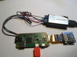
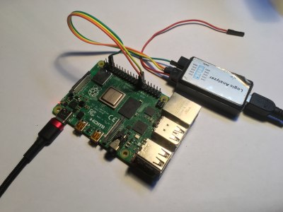 I’m using a $10 logic analyzer you can get off Aliexpress or Amazon, a laptop, and a Raspberry Pi with an SD card and a power supply. Here, it is wired up – you only need three female-female wires, two signals and one ground. “SD” and “SC” sounds like I2C – typical I2C frequency is usually either 100 kHz or 400 kHz. A good rule of thumb is to set your frequency to be three or four times larger than the clock frequency of the data stream you’re about to capture. As such, I plan to set my logic analyzer’s sample rate to 2 MHz. If it turns out to be too slow to catch up with the data being transferred, I can increase the sample rate and just do the sampling again.
The software I’m using is Pulseview – it’s a wonderful GUI for logic analyzers, and can interface to a large variety of logic analyzers. It’s open-source, Linux-friendly, hackable and has good UX, even if it’s not recently maintained. You can install it from your distro’s repository, or download the .exe if you’re on Windows. With the logic analyzer connected, I plug it into my USB port, launch Pulseview, set the sample rate and reading duration, which can be infinite, disable all channels except the two I’m interested in, press ‘Capture’ and plug the Pi into power.
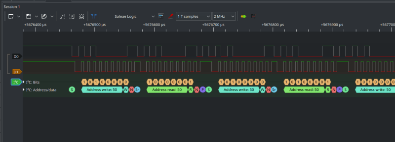
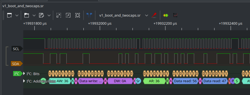
After I plug the Pi in, logic levels on both of the pins go up as 3.3 V power appears – and, after a few seconds, there’s a short burst of activity on these two pins. Zooming in, the activity does indeed look like I2C – and in Pulseview, it’s quite easy to decode! Press the “Protocol decoders” button on the settings taskbar, type “I2C” on your keyboard, select the I2C decoder, then doubleclick the decoder tag on the left and select which channels are SCL and SDA – it’s easy to tell, SCL will look like a clock signal with equal highs and lows, while high and low intervals on SDA will vary; on the picture above, D1 is SCL and D0 is SDA. Zooming in on the I2C events decoded, we can see that this activity is I2C requests to read data from the address 0x50, and these requests are followed by NACK events (red marker), which means they don’t receive a response.
Now, if you’ve looked into Raspberry Pi HAT design, you might already guess that these I2C requests are coming from the Raspberry Pi bootloader, which is looking for the I2C EEPROM containing on-HAT device information, so that the Pi can load Device Tree overlay data from it and use that data to configure any hardware on the HAT connected. You don’t have to rely on whatever little information is available online about this process – with a logic analyzer, you can investigate what actually happens, find any hidden features and caveats, so that even proprietary hardware is as little of an obstacle to you as possible.
Fooling The Pi’s Proprietary Firmware
 This is a simple example of what you can do with a logic analyzer and a Raspberry Pi with a 40-pin header. Let’s ramp it up! On the Pi board alone, I2C is used in a few different places – HDMI display configuration, Pi camera configuration, a GPIO expander on the Pi 3 that compensates for lack of IO on the CPU – there’s plenty. You can explore all of these for fun, but, let’s achieve an actual practical goal.
What you could do with all that I2C? Well, here’s a small but situational problem with the Raspberry Pi cameras – they’re not hotpluggable; and if there’s one thing we know for sure, it’s that you don’t always have to respect limitations of your technology. You might not always want to have your Pi camera dangling around on a cable, for instance – that’s a bit subpar, it’s fair to only want to have the camera plugged in if you actually want to take a picture. Well, now we can actually check what’s happening on the camera I2C bus, and if that’s the culprit, making it hotpluggable sounds exactly like the kind of thing we could pull off – plus, we’re going to be fighting against the proprietary firmware on the Pi while at it!
 Technically, the Pi firmware will only recognize a Pi camera if it’s plugged in during boot – the closed-source bootloader checks camera presence during boot, which certainly implies communication over I2C, maybe it’s even setting some camera-specific I2C registers; if you don’t have a camera plugged in during boot, that won’t happen and you will need to reboot your Pi for the camera to work. But after boot you can unplug the camera and plug it back in, and it will work just fine!
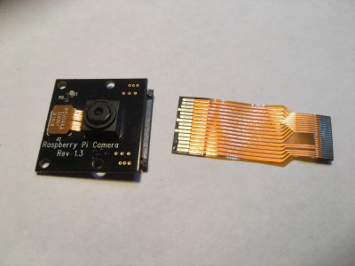
Given this riddle, my guess is that there’s really no reason why a Pi camera couldn’t work if it’s plugged earlier, apart from the inflexible on-boot detection logic. The default camera FPC is also mechanically not hotplug-capable, so I’m going to work around this by modifying the FPC so that the GND pins make contact first when you hotplug it. The main problem stays, though – the Pi bootloader is closed-source and we can’t modify the detection logic, making it so that it only runs once software actually tries to access a camera. We can, however, hack it by wiring up our own MCU to that I2C bus and making it present as a camera on the I2C bus!
Here’s the roadmap – we wire the logic analyzer up to the Pi Camera I2C bus, see what kind of activity happens as the Pi boots up, then we add an MCU that taps into the camera I2C pins – a RP2040 will do nicely, given that it can function as an I2C peripheral. The hardware needed for such a hack is minimal – a microcontroller board and a few jumper wires, that’s it.
Hack A Pi With A Pi
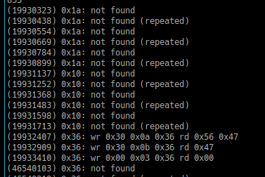
 After soldering onto camera I2C bus pullup resistors on a Pi Zero, I captured the on-boot I2C communications with the v1 camera plugged in, and here’s my findings. There’s three I2C addresses queried on boot – 0x10, 0x1a and 0x36, my camera responds to 0x36. Apparently, 0x10 is used for the sensor on the Pi Camera v2, and I’d guess that 0x1a is the 12 MP camera.
With the v1 5 MP camera I used, nothing is written into the registers – it seems there’s only three transactions that read from the camera sensor’s registers, with each transaction first sending two write bytes, which is typically a register address in such transactions. Having two-byte register addresses does make these transactions look a bit weird! That said, being able to unplug the camera and plug it back in without problems does lead me to believe it shouldn’t be a problem.
 Now that I know what’s happening under the hood, I’m going to unplug the three jumper wires from the logic analyzer, wire them up to a small RP2040 board I have, and get hacking on the software side of the project. If I can get I2C peripheral-emulating firmware going, I’ll have Pi camera v1 hotplug operational for all of my portable device building purposes! Just like this, with a logic analyzer and three wires, we have figured out a way to add hotplug capability to the Raspberry Pi camera – something known as impossible, until we decided to probe it.
 This kind of hack is where a logic analyzer is the best tool for the job, and you might have noticed that a few crucial parts of this hack, namely, sniffing the I2C data being transmitted, aren’t feasible without a logic analyzer.
It also gives you insights into how proprietary things work – both in the HAT EEPROM detection example and the camera detection example, we can see that every failed transaction is repeated three times, and you wouldn’t be wrong to guess that the Raspberry Pi bootloader code has an I2C transaction wrapper that retries I2C transactions in case a transaction spuriously fails – a good practice through and through!
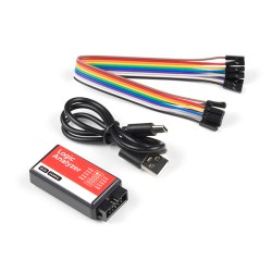
Thinking about getting a logic analyzer? The analyzers are great for what they are and will be enough for majority of the tasks, and they go for around $10 on typical online marketplaces – more than enough for all the things you might want to probe. You can also use a Pi Pico as a logic analyzer – though you will find that you likely have to compile Pulseview and the under-the-hood software yourself to include support for that, doable but less straightforward than using one of the FX2-based analyzers with stock Pulseview support.


“A logic analyzer has a number of digital inputs, and it continuously reads the state of these digital inputs”
No. It reads the state when you start the capture, or when a pre-defined condition (trigger) occurs.
Nope, it “continuously” captures data, and it only uses the trigger to organize the data and stop the data capture (after a while) and usually both pre and post trigger data is available for analysis.
It does not “continuously” capture data, it samples every tick of the clock at a rate defined by the control software and in general, for these ultra low end analyzers, captures until the memory is full at which point it stops. In regards to your response to ono, whether or not the analyzer is capturing before the trigger occurs is highly dependent on which specific analyzer you are talking about, so you’re wrong there too.
this analyzer has no memory to speak of afaict and it is a streaming analyzer – it sends the values constantly over the USB interface, which is what causes the 24MHz max limitation, as far as I can tell
Of course it has memory, I am not aware of any logic analyzer that doesn’t buffer samples in memory and while the memory in this one may be small due to the constraints of the SoC used, the memory is absolutely required to buffer the samples before they are sent over the interface. USB isn’t time deterministic enough for direct sampling like what I think you are speaking of. I suppose you could do it but it sounds like a recipe for problems.
The FX2 based LAs continuously sample the logic levels at its input pins and buffer up to 3 USB HS Bulk packets (i.e. 512 byte) for transfer to the host, while it fills the 4th one (quad buffered).
For the FX2 LAs, start triggers are completely implemented host side. It can capture several Gigasamples, although the FX2 has just 2048 byte of buffer memory.
(I am a former Sigrok developer, and I have written parts of the FX2 FW, so I know what I am talking about.)
Arya, what logic analyzer are you using here? The images are a bit too low-res to tell. As I don’t own one yet, I’ll definitely take recommendations!
The first logic analyzer looks like any of the 8ch USB logic analyzers on AliExpress et. al, and the 2nd logic analyzer is SparkFunTOL-18627
Oh, my bad! Both of these are the same hardware, FX2-based analyzers, you should be able to find them with “8Ch 24MHz”, Sparkfun’s got a nice one that sells for $20 and I suspect it might have a bit more inside wrt input protection, but any eBay/Ali/etc $10 one should do wonders!
Well, if you have the sparkfun variant, then pop off the lid, make some photographs and put them on the Sigrok website. I doubt the sparkfun variant has better input protection than the chinese versions, but I’d like to know for sure. I bought several via Ali (long before sparkfun sold their own variant) and they tend to look a bit differently inside. I even got one with a CY7C68013A-100 (Yes that is the 100 pin variant instead of the 56 you see more often). I also wonder if the soldering quatlity of the sparfun is any better. It would not surprise me if they are just the same but over twice the price.
I’d like to know for sure, but, this is just a guess! If anyone has the Sparkfun variant, I’d be very much interested in PCB pictures!
They’re not on the FCC internal views site.
Sparkfun only has one item listed.
Sparkfun’s FCCID = 2ASW8
It could just be pending, might take years. You know, ‘good enough for government work’.
Thanks Josh and Arya!
These small boxes are all pretty much clones of the original Saleaeaaeae. They have a Cypress
CY7C68013A in them and some protection circuitry for the inputs. This microcontroller also does not have firmware, Instead it downloads it’s software via USB DFU when you plug in the cable, and the Sigrok project has it’s own software, so there is no software infringement whatsoever.
There is also a list of supported hardware on the Sigrok site:
https://sigrok.org/wiki/Supported_hardware
I have used these boxes for a few years, and have been looking for an upgrade for quite a while too. A few days ago I ordered a Kingst LA2016 https://sigrok.org/wiki/Kingst_LA2016 I hope it is supported well by Sigrok, or else I have to revert to the original software (which apparently also runs under Linux), but I’m quite apprehensive of installing or running any software that comes out of China.
I own LA2016 and I’m interested if you manage to get it to work with sigork.
Have you tried it yourself?
It is unfortunately not completely plug and play. You have to extract the bitstream for the FPGA from the vendor software. This is describet at:
https://sigrok.org/wiki/Kingst_LA_Series
Both LA2016 and LA2034 work perfectly with sigrok / pulseview.
Yes, you just need to put the right firmware file at the right place on your system to make things work.
They are not part of sigrok bc they are closed-source binaries.
USB DFU is a standard protocol, while the FX2 uses a proprietary protocol. USB DFU is much more versatile, while the FX2 protocol just lets you write into the internal SRAM – though you could load a FW which then implements DFU ;-).
A few years ago I posted a mini tutorial on how I use one of these boxes to do software debugging on microcontrollers. It nicely captures debug data and timing, together with marks of when ISR’s trigger and how this interact with other hardware such as the UART. I also wrote a simple but effective header file to quickly turn the debug info on or off. Just search for the “debug.h” file on the website link below:
https://www.avrfreaks.net/comment/2421756#comment-2421756
This is how I’ve been doing debugging since the early ’90s (with big MSOs back then) and it’s the only way to really see what’s going on, particularly in a heavy-interrupt real time system.
One of the less obvious benefits is that if you’re using a decent analyser, it can be set up to trigger on a particular glitch, be left for as long as it takes for the condition to trigger (sometimes days…), and you can see exactly what led up to it.
Thanks for sharing that, I needed that. Plus I have a logic pulser I’m trying to figure out.
… And about the Sigrok project…
I find it quite sad to see, but Sigrok seems to be limping along in the last few years. There are hardly any updates or other sorts of progress. I wish I could put some more life into the Sigrok project, but I don’t know how. It would be really nice if there was some decent Logic Analyzer hardware with official support for Sigrok. At the moment I have a Kingst LA2016 on order by lack of the ability to get something with official Sigrok support. I would gladly pay a bit extra for Sigrok support.
Maybe an upgrade of the old FX2 to the much more capable FX3 is a path for Sigrok to get it’s own Hardware, but apparently the FX3 fast USB is a bit problematic concerning drivers. Unfortunately I can’t focus much on writing software anymore, but I can still do some PCB design in KiCad, and am willing to spend some time on a PCB design.
yep! I’m on the mailing list, and, it’s sad to see the project unmaintained, to the point where I’m wondering what could be done about it. I’ll keep this in mind, thank you for sharing – I believe the sigrok ecosystem could use some love lately, and I’m glad to hear I’m not the only one who feels this way!
A while back Hackaday published a project using a Raspberry Pi Pico as a logic analyzer. You can’t beat that for cheap, especially if you already have the Pico. I was debugging an I2S interface and used the Pico to see what was going on. Saved me loads of time.
yep, that one’s wonderful, I linked the article in the closing paragraphs, here it is for anyone interested! and, yes, I2S’s absolutely one of these interfaces where a logic analyzer is a surefire way to figure out common problems ^^
Right! I see you wrote that article, too. Thanks!!
yeah, at the time I was seeing some good activity on the sigrok mailing list, and I thought “this is going to be merged soon” – sadly, that very much didn’t come to be =( however, it should be possible for you to easily compile your own Pulseview install with the RP2040 patches, or, perhaps, the GitHub thread on the RP2040 support has an even better solution I’m not aware of!
You don’t even need to buy a logic analyzer if you already have a Pi Pico (RP2040) as you can load up logic analyzer code right on it, and it actually makes a great logic analyzer!
Lacks input protection though and level shifting.
So it’s exactly like those salea clones from the article. No level shifting or input protection to be found on those!
Love this, but I already bought a scope with analyzer and decode functions. This may have saved me $$$. $20 verses $300 for the USB pc based scope, darn. Well I can always do more with the scope but my main idea was the decode for i2c, serial, etc., to check what my code was sending and when.
They’re Saleae Logic 8 knockoffs, only without the level shifters, based on a Cypress CY7C68013A USB microcontroller. Often sold as a CY7C68013A development kit, which technically isn’t wrong, but leaves out the fact that the USB ID has been matched to Saleae’s one, so that the original software detects it as genuine.
But there’s nothing wrong with using it with open source Sigrok/Pulseview.
You can also buy a generic CY7C68013A development board (with two dual row headers). This has another ID code and Sigrok accepts it as a 16 channel Logic Analyzer. Disadvantage is that it does not have a case, nor any input protection hardware.
Is the format of these log files specified somewhere? I do MCU simulators and it would be nice if the simulator could export data for visualization with pulseview when it is being executed on PC.
which log files specifically are you wondering about?
I mean here it mentions that there are a bunch of formats that the program can import: https://sigrok.org/doc/pulseview/0.4.1/manual.html#_import From the many available formats which format would you recommend to generate by a simulator? I simulate real time protocols on PC. For a start I would put the signals of the simulated UART lines into a file to visualize them.
Actually, I think that the capture occurs on some edge of the clock that is gating the sampler. Devices like this use very (relatively) low sampling rates, so if your target signals are faster than 1/2 of the sampling clock, your results will be incorrect. See Nyquist for an explanation of this issue.
Also, logic analyzers operate in the digital domain, which means they cannot tell you much about the quality of the signals you are monitoring. For that you need an oscilloscope and a much higher 5x or more sampling rate.
Overall, this is a fun toy that will help people new to the field start to understand how things work. However, like many toys that are being used as tools, sometime they give incorrect information and mislead the user. Be aware of the limitations and have fun!
The one thing that would make this article better is the pico spoofing code. So much build up for no execution.
I’d add that while these little 8ch jobbies are absolutely great go-to devices, a “classic” 80s or 90s logic analyser from HP or Tek won’t set you back much and can still be extremely useful.
My old HP has 65 channels, 10 nSec resolution, and protection good to 48V. What it /doesn’t/ have is arbitrarily deep memory and an active support community which is continually writing new decoders.
There might be actual reasons, besides the bootloader inconvenience, about why the camera is not hotpluggable. For hotplug to be really safe (for the device itself), there are a number of concerns about sequencing of pins during the connection, possibility of ESD discharge, transients at connection, etc. For example, USB connectors are made for hotplug, the length of data and power pins is intentionally different to be sure that the power is already connected when data connection is established. And if a device doesn’t have the proper protections on the pins, it can just have some I/Os burned by a voltage transient or ESD discharge at connection. I’ve seen an industrial camera worth 5k going out of service because its CameraLink interface was not designed for hotplug, but the camera was hotplugged (note that 99% of the time, it was working fine, but it doesn’t mean it will always work without destroying some hardware).
oh I get that! Hence the FPC mod picture where I shorten all pins except GND, so that GND pins make contact first – I accidentally cut off one of the GND pins on the end, but, it gotta be good enough still. well noted, thank you for the explanation!
At first I thought you were running the logic analyzer software on the RPi itself! Then I saw you were looking at signals during boot up and realized you had a second computer off to the side.
I have a 16 channel Saelee on loan from a client, and an Analog Discovery 2 which has logic analyzer capability. But I’m a little gunshy with them when I burned up two channels last Fall. I’m tempted to get a couple of these low-cost modules you featured here to toss in my toolbox for use when I’m on site. If I fry a channel on a $20 gadget, I’ll feel less guilty than on a $200++ one. Great writeup Arya
Any update on the code? :( I can’t seem to get it to work.
oh? what specifically is it that you’re trying to get to work, could you describe in more detail?
Love these articles by Arya. Worthy of taking notes, and have bought a logic analyzer from AliEx just to follow along. Not quite working yet with older Rasp., and not quite ready to ask a question either.
This is one of those series that if it was released as book you would not regret buying. What is more Comment section is also great.
If authors here had something like “buy me o coffee” pushbutton I guess it would be pressed more than few times.