Soldering pin headers by hand is a tedious task, especially when your project has a huge number of them. [iforce2d] has a large number of boards with a lot of headers, and has created a rather special CNC machine to to do the job. It’s a soldering robot, controlled by LinuxCNC and you can see it below the break.
Superficially it resembles a 3D printer made in aluminium, with an X-Y movable table and a Z-direction represented by a soldering iron and solder feeder on an arm. The solder feeder uses a Bowden tube, with a 3D-printer extruder motor pushing the solder wire down a PTFE tube and finally into a fine aluminium tube from which it’s fed to the iron tip.
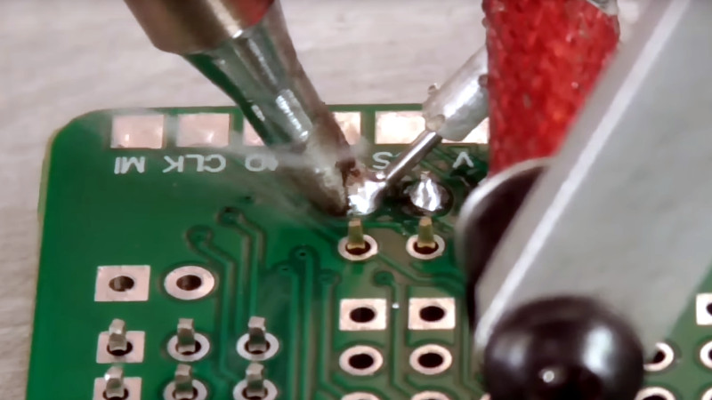
Though he’s done a beautiful job of it, creating the machine is not all that’s required, because the tool path requires more attention than simply moving the iron to each pin and supplying some solder. There’s a need to consider the effect of that heat, how much each pad needs, and how much neighbouring pads contribute.
We’ve had repetitive soldering tasks just like this one though not on this scale, so we can understand the tedium this machine will relieve. We can’t however help being reminded of XKCD 1319.


Awesome!!!!
I thought the xkcd link was going to go to https://xkcd.com/1205/
That said, sometimes the fun is just building it…
So…
The soldering robot, like a human, needs a coffee mug at its workstation?
Although food and drink at a soldering station suggests poor safety practices.
Now I’ll wait for the Australians to respond that safety is silly and they regularly have solder paste with their Vegemite’n’toast. Or something like that.
There is a video clip of an emu and a kangaroo having a soldering competition – the crocodiles wanted to have a go too, but that human, Crocodile Dundee, was running the comp and told the crocs to buggar off. For the record, the roo won.
Fair dinkum.
Yes, it does
So in the late 90’s they did a study Coffee mugs were found at the workstations of all productive cnc machines, humans at only a fraction of productive machines. They therefore correctly summarised that coffee was an essential element of CNC machines.
Interestingly they found different and unrecognised mugs at many broken machines but when the mug disappeared the machine was once again working. They have yet to figure out why.
Looks like a job for a wave solderer.
Though, truth be told, back when these were a thing we didn’t use the wave soldering machine for a run less than a few dozen boards, because of the setup effort: it was quicker and cheaper to just have the women(*) on the factory floor solder them up.
(* yes, 100% women doing factory production soldering. Sorry, this was 1981. Men couldn’t solder worth a damn then.)
Well you cant wave solder if there are components on both sides or its already assembled or there are heat sensitive parts, really a lot of limitations to wave soldering.
That said uh just use solder paste and a directed air gun? But hey sometimes its just the fun of making a thing
You’re right there are some limitations, and the board should be designed with wave soldering in mind. But current wave solder processes can solder double-sided boards, including mixed through hole and surface mount parts, and specifically including boards that have previously-soldered SMT parts.
There’s nothing on the bottom of the board presented here, so it’s easy, and an ideal candidate.
Only makes sense if you happen to have a wave solderer and at least a few dozen boards to process though.
Sorry Paul, I wasn’t born until 1982. If you need anything soldered by a man now though I’m available.
These headers have SMT equivalents anyway
No they don’t. The three row headers are through-hole only.
Well, it’s nice and all, but why not simply repurpose the cheapest 3D printer?
The XY table is the same. Z drives the soldering iron up and down. Extruder delivers the solder. Heated bed switch (or fan) turns the iron on and off. G-code all round. Done.
If the answer is “because I can” then fair enough.
Probably so all is out of metal and so he can control the angle of the soldering iron better (which is usually not something 3D printers can, unless they are quite expensive).
Finally, sometimes it’s easier to do something on your own, than trying to make an existing design do what you want.
The soldering iron is in a fixed, but adjustable, position. It is not motorised.
Also, the belt drive for the table is overly complicated. Again, maybe “because I can”.
It looks a bit overcomplicated.
However a traditional 3D printer moves the head along the x and y axis and the plate only moves along the z axis.
In his system the “head” remains immobile, but the plate moves along the x and y axis.
Also, I still don’t think that it’s very practical to mount a soldering iron on a 3D printer head at an angled position. Doable probably, though it will likely collide with rails or other parts, and the cable will come out at an impractical angle and will need to be guided out of the way as well, especially while the head is moving around.
Then you need to add a feeder for the solder, which also should not collide or get entangled with anything, while the head moves around.
It’s just harder to get that right, compared to having only the baseplate move.
3rd prhase should be: In his system the “head” remains immobile, but the plate moves along the x and z axis. (x horizontal, y vertical, z depth)
I considered all of your points, but frankly none of them are valid.
Ah, since there is only one approach to a problem, all others are invalid.
I am glad you found a solution with no drawbacks that is better than all the rest. I thought this site was about learning and getting inspired.
Not at all. I said an off-the-shelf 3D printer could be modified to do this. You said it couldn’t, for various reasons. I say those reasons are bogus, therefore I still think an off-the-shelf 3D printer could be used.
The project its self is nicely built and executed, but I don’t understand why he built the whole thing. I completely understand his motivation for wanting more automation, but he already has a machine capable of milling aluminimum, and just adding the soldering head to that would have saved a whole lot of manufacturing and reduced the costs a lot.
Alternatively, he just could have bought an EUR50 soldering pot and solder such a board in about the same time as it takes to clamp the PCB in his soldering contraption.
And last. I would be quite interested in a DIY method to build a solder fountain. It’s principles are quite simple, as far as I know they melt the solder, put it in a small pipe with magnets on the side and push some current though the molten solder, and this pumps it out of the tube. Just having some detailed photographs of the internals of commercial units would already be a good start.
soldering pot will thermal shock your board bending it in the process
And shortens the lifetime of the epoxy in the board.
haha this article made me look at videos of wave soldering and solder pots and as someone whose hands shake almost too much for even through-hole soldering, my imagination loves the idea of a solder fountain. dip it like it was dinner going into a fondue fountain.
but the longer my imagination dwells on it the more terror i feel
Selective soldering machine does exactly this :)
Very cool build! After watching the soldering process, it looks like he would benefit from cleaning the soldering tip periodically. Should be able to program that in by mounting a brass brush to the plate and travelling through the bristles a few times.
I wanna say Prusa calls these wipe towers or something along those lines.
To give a bit inspiration of what is possible and how to reproduce a somewhat similar principle, have a look at these robotic soldering systems.
https://www.jbctools.com/automation-category-25.html
So called barrel solder tips seem to be ideal for THT soldering.
https://www.jbctools.com/r470041-barrel-cartridge-o-15-product-1986.html
Finally, a desoldering nozzle could be used to apply solder, instead of applying a vacuum to remove solder. But that may not be as reliable as other options mentioned above.
https://www.simpex.ch/en/shop/production-technology/soldering-tips-and-nozzles/ds-112-desoldering-nozzle/
Desoldering nozzle would burn off the flux before the solder hit the joint…which will lead to cold solders.
I get where you were going with that though.
But you can also turn that around. You can apply flux to the PCB and use solder without flux. That is also pretty much how selective soldering with a fountain works.
Possibly cheaper from Hakko, but similar concept, Chisel V-groove and Chisel Slot:
https://eleshop.eu/hakko-t37-series-soldering-tips.html
I believe that if you lift the solder gun vertically you will have less bridging. And you can try to use a bit less of a solder. You can also add a blower to cool the joint. And you cand add a laser termomether to check the joint temperature.
Or you can switch to paste solder abd heat gun.
I just use SMT headers, seems simpler than re-inventing a selective solder machine
Where do you buy your 3-row SMT headers?
Recently saw an adafruit video where they showed off a “fountain” wave soldering machine. Basically only wave solders a small area via a flowing fountain of molten solder coming up a metal tube and falling back down into a pool below to reheat/recirculate.
Could have used that soldering all those 100-pin sockets onto my Altair’s S-100 motherboard.