Once upon a time, if you wanted to generate some waveforms, you needed to buy an expensive off-the-shelf function generator or whip up a big pile of analog electronics. Not so today, when you can grab a fast microcontroller off the shelf and have it squirt out whatever fancy waves you might desire. That’s just what [rgco] did to build this nifty arbitrary wave generator.
The build improves on prior work by [rgco] with the Arduino Uno, with which they built a device that could output at 381 kilosamples per second, with each sample update taking 42 instruction cycles. Thanks to the Pi Pico’s faster clock speed and certain performance optimizations, they were able to up that to a mighty 125 megasamples per second, using the DMA and PIO subsystems to output a new sample every single clock cycle.
The result is a cheap function generator you can build with a Pi Pico and a handful of resistors, which will probably cost you the grand total of $12. It readily outperforms, at least in regards of speed, devices based on the AD9833 function generator chip, which only runs at 25 megasamples. Plus, that chip can only output sines, triangles, and squares!
Even a passable function generator can be a useful tool to have in the workshop, as we’ve seen before. Video after the break.


Now THIS is a cool project. I would like to express my thanks to the author and of course the person who did all the leg work on this. Well done!
Reminds me one of my old college assignments. To generate a sine-wave via digital means.
The easiest trick is to indeed just generate the waveform in advance and than set-up a DMA channel to go nuts and constantly pump values to whatever means of Digital-Analog conversion you got. Be it a resistor ladder, a internal DAC or an external one. Its pretty much set and forget. Though if you want good results you will want to read up on how to do Direct Digital Synthesis proper to generate a more accurate waveform.
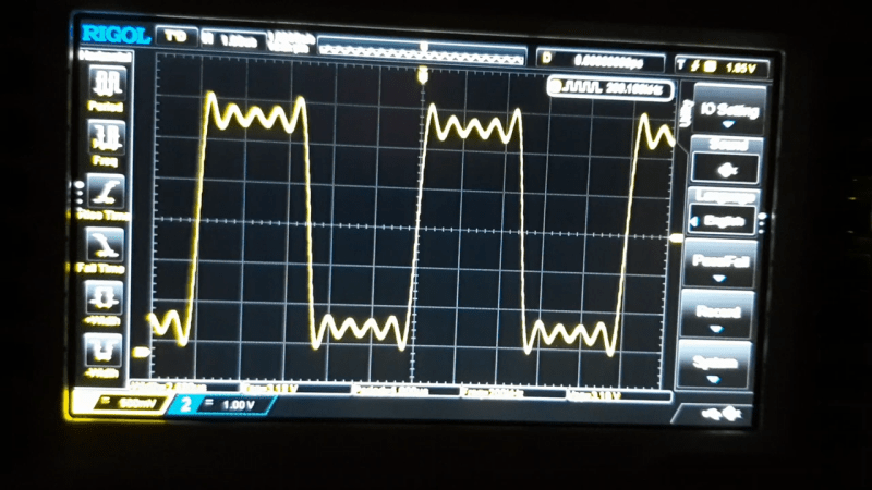
At the moment I see this project just as a proof of concept, and if it really pumps out 125Msps without glitches that is a feat worth mentioning.
And of course it needs more for a “real” application. I have to get DMA working on STM32 some time… One of the projects I am interested in is to pre-calculate DDS values, and combine those with amplitude in an array and then output it to R-2R DAC (Goal is about 12 bit accuracy and 16 bit of resolution for fine amplitude and offset control).
Both amplitude and frequency adjustment would then trigger calculation of values in a new buffer and (hopefully / mostly) seamless switching between the buffers. Coarse amplitude / offset would then be added with external attenuators / amplifiers.
The goal is to make a capable AWG with minimal hardware cost, and that is also easy to reproduce. The biggest nuisance is that the resistors for the R-2R network need to be hand sorted (to 0.02% for 12 bit) but that is doable with a simple DMM and half an hour of time.
I also am glad the project this article links to mentions the sorting of the resistors R-2R can be good, but it all depends on the resistors. It is not used much in industry because of this. Accurate resistors are more expensive then a “real” DAC, and factories do not have time for hand sorting. Drift may also be an issue. It is also noteworthy that only some of the MSB need this accuracy. It really does not matter if the LSB deviates. Even 10% is insignificant for the LSB.
Pseudonoise with Arbitrary Amplitude Distribution–Part I: Theory.
https://ieeexplore.ieee.org/document/5008973
A 555 wulk do the sane job
how you generate an arbitrary waveform o thousands of points you upload from file with an 555?