If you are making certain precision measurements, you know you need to terminate the connections with the right impedance, normally 50 ohms. Proper termination minimizes reflections on the line which can disturb measurements. Some instruments already have 50 ohm terminations, at least optionally. If not, you usually use little connector shells with the right resistor inside. [Joe Smith] decided to see if he could improve on the normal terminations using circuit simulation techniques. You can see a video of the work below.
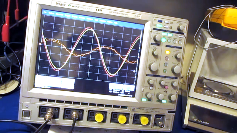
In the process of testing, he also needs a resistive splitter, and, just like with the terminators, he shows you what’s going on inside. It was easy to compare since he had a scope that could independently set channels to have a 50-ohm termination or a 1 megaohm termination.
It is easy to see the signals don’t match without extra termination. You can also use the subtract function to show the exact error waveform. What’s more, since the signal is split, mismatches on one input will cause errors on the other input. There’s a solution for that, of course. The presumption, of course, is the LeCroy scope’s internal termination is “good” but this is an excellent method to at least compare two setups, even if you don’t know which is the best one.
Scopes aren’t the only place terminators come into play. Calibrating a VNA is another use case. You think of scope inputs and probes as just simple wire connections. Nothing could be further from the truth.


Thanks for linking to the video – I thought the topic was well explained by the presenter.
I am but an amateur, so while I am able to setup proper Spice simulation in KiCad, I mostly keep to the simple tools by Paul Falstad. Despite their numerous deficiencies, they simply are the fastest for tinkering.
Simulating the described compensation using the Analog Filter Tool, everything looked fine initially. The phase shift was too sharp to my liking, though:
https://tinyurl.com/29nb27wb
So I have copied the circuit over to CircuitJS for time domain inspection and my hunch that there would be peaking proved correct:
https://tinyurl.com/ykveurw7
When analyzing analog filters, always check both time and frequency domain to make sure you are getting the expected results.
“normally 50 ohms”
Though it’s likely at home someone’s seen 75 ohms, since that’s what TV uses, as well as a few other things.