The oscilloscope is probably the most versatile piece of test equipment you can have on your electronics bench, offering a multitude of possibilities for measuring timing, frequency and voltage as well as subtleties in your circuits revealed by the shape of the waveforms they produce.
On the front of a modern ‘scope is a BNC socket, into which you can feed your signal to be investigated. If however you simply hook up a co-axial BNC lead between source and ‘scope, you’ll immediately notice some problems. Your waveforms will be distorted. In the simplest terms your square waves will no longer be square.
Why is this? Crucial to the operation of an oscilloscope is a very high input impedance, to minimise current draw on the circuit it is investigating. Thus the first thing that you will find behind that BNC socket is a 1 megohm resistor to ground, or at least if not a physical resistor then other circuitry that presents its equivalent. This high resistance does its job of presenting a high impedance to the outside world, but comes with a penalty. Because of its high value, the effects of even a small external capacitance can be enough to create a surprisingly effective low or high pass filter, which in turn can distort the waveform you expect on the screen.
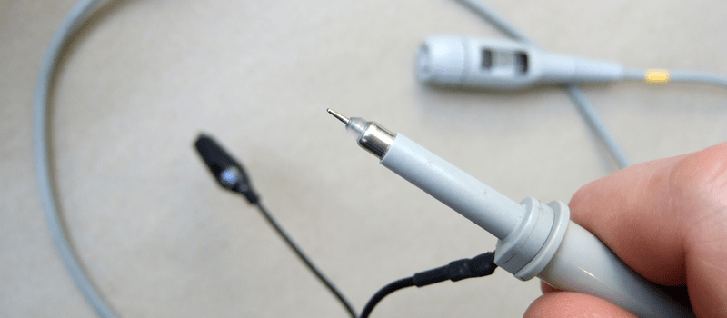
The answer to this problem is to be found in your oscilloscope probe. It might seem that the probe is simply a plug with a bit of wire to a rigid point with an earth clip, but in reality it contains a simple yet clever mitigation of the capacitance problem.
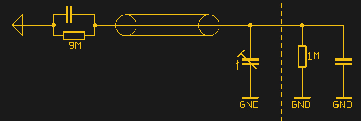

One of the compensation capacitors will be adjustable, to fine-tune the response. The ‘scope will have a calibrated square wave output, usually at 1 kHz, to which the probe is attached, and then the capacitor is adjusted until the wave displayed on the screen is truly square. Too much capacitance and the probe has the effect of a low-pass filter, while too little and it becomes a high-pass filter. It should become a semi-regular part of bench maintenance to check your probe against the calibration terminal, and to adjust it accordingly if the displayed waveform is not a square wave.
Highs and Lows
The probe is designed to present a high impedance to a circuit in situ, and not to distort the resulting displayed waveform. However there are times when it is necessary to measure an output that expects a low impedance, such as a 50 ohm source. In this situation the source must be terminated with the same impedance, so it should be fed into a 50 ohm resistor.
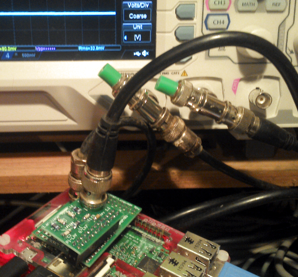
Some ‘scopes have a 50 ohm input mode, making this a matter of button pressing. Otherwise, a measurement can be made across the termination resistor, but since the impedance has now been reduced to a point at which small capacitances no longer have a significant effect, it becomes unnecessary if the cable to the oscilloscope is reduced to the barest minimum. In these cases you can dispense with the probe entirely if you have a BNC T-piece and a 50 ohm terminator, and put both terminator and T-piece on the end of your cable directly coupled to the BNC socket on the ‘scope.
For many readers this basic primer on the operation of an oscilloscope input and probe will be old hat. But I remember my first oscilloscope, and how it gave me odd-looking results because I was too young to have been taught about probe compensation. When you get your first ‘scope it’s tempting to think that the ‘scope is the main event, without realising that it’s only as good as how you connect it to your circuit under test.


I’ve repaired an old probe tip with a 1x – 10x switch because somebody had poked at line voltages with it and blown the small resistor inside. The whole scope was discarded as broken, but I discovered only the probe was actually damaged.
Curiously enough, the blown resistor was 46 Ohms 5% and the other one was 300 Ohms 5% with a black mystery blob in series. The switch selected between those two branches coming from the tip.
The input impedance of the scope was 1 MOhm.
>The whole scope was discarded as broken
Some people throw things away for no good reason.
I have 3 semi-modern Tektronix scopes (new enough to have USB) that I pulled from garbage piles while working as a lab instructor. In every case, the problem was a blown fuse.
In those cases, I think the problem was rather “there’s room left in the budget and we have to spend it” – or – “I want new toys”.
Reminds me of when I repaired clone PC’s 20 something years ago. A PC would intermittently fail and the part supplier would test and return it saying no problem found. Running 12V from the power supply over the leads of the main ASIC’s gave that RMA a surefire replacement guarantee.
Sounds like the somewhat risky tip I got from a BT engineer many years ago for logging a fault on the phone line. If you were having difficulty persuading the call centre minions that you knew what you were talking about, and that the copper pair in question was without doubt the cause of all of your woes, he suggested the gentle insertion of a 1/4″ flat bladed screwdriver in to the socket to tickle the contacts inside. Apparently this would trip the short circuit alarm on the exchange and this would be flagged up for the next minion you called at the call centre as a hard fault on the line.
Actually what I think he said was something more on the lines of “I do not of course suggest that you *ever* do this, and if you say you got this tip from me, I will flatly deny ever uttering such a suggestion”, so in light of that… all I can say add is “I do not of course suggest that you *ever* do this, and if you say you got this tip from me, I will flatly deny ever uttering such a suggestion” };¬)
FWIW there is around 50V DC on the line, and considerably more in the form of pulses when it is ringing so any tinkering with any POTS line is done entirely at your own risk.
That’s just poor service for that era. Sure intermittent are a pain and can take longer to conclusively repair but there is still no excuse for not being able to diagnose an intermittent.
On another note I heard a phone conversation about an EFTPOS Pin pad – that thing you swipe your card through in shops. It went something like this –
CSO: The cards are gripping when customer swipe so they have to swipe a number of times.
Warranty Tech: We only replace them if they’re broken. We don’t replace them if they’re difficult to use because they can serviced.
CSO: I will just go and see if it’s actually broken ….
Background noise: Smash Smash Smash
CSO: It’s definitely broken, where do I send it.
I know its a few years late.
The probe that is described here and repaired was probably a 50 ohm high bandwidth probe. Which is why it will blow up on more than a few volts DC or AC..
Oh, so thats how it works! Didn’t know these things, so thanks, greatly appreciated!
Really enjoying this little primer. Is there gonna be a more in a series?
+1 for more in this series!
+1 for more
“In these cases you can dispense with the probe entirely if you have a BNC T-piece and a 50 ohm terminator, and put both terminator and T-piece on the end of your cable directly coupled to the BNC socket on the ‘scope.” Or you could get a feedthrough terminator and do away with the T. :)
Also an interesting note about scopes and probe input impedance, generally the higher bandwidth your probe is, the lower the input impedance is, especially when you’re talking about high-speed differential probes. A 1GHz passive single-ended probe might have 10M ohm input impedance, but a Tek P7380 (8GHz diff probe) has 50k ohm single-ended and 100k diff impedance, and the 25GHz+ P7600 has (minimum) 225 ohms at 1GHz and 100 at 25GHz.
Those feed-through terminators are too darn expensive!
You can find BNC tees and a BNC terminators on the second-hand market for only a few US dollars each, so that has been my go-to method for years.
I’ve always wondered why the calibration signal is only 1kHz; it seems strange to calibrate a 100MHz scope (or whatever your scope’s bandwidth is) against a 1kHz signal. Does the test signal actually include all the harmonics up to 100MHz (or higher)?
I generally get a high-quality signal generator to generate a 10MHz or so square wave (at high-Z setting) and calibrate against that.
Why only 1kHz?
Because with a high frequency signal you’d be fighting against unwanted reflections and other non-linearities in the system. The point is just about the sharpness of the square wave.
It’s not about the signal’s frequency as such. The 1kHz isn’t important. The key is in the edges of the signal: the rise and fall times. That’s where all the harmonics are because those edges can only be expressed mathematically by a sum of sine wave and its odd harmonics. As you can see on e.g. https://upload.wikimedia.org/wikipedia/commons/b/b5/Spectrum_square_oscillation.jpg , an ideal 1kHz square wave has infinite odd harmonics. I haven’t looked at how fast the rise/fall times on those calibration outputs are, but at least now you know why they use a rectangular wave and why the 1kHz isn’t important.
That is true, but it is not the reason why the compensation signal is at 1khz. This is necessary since the crossover frequency of the probe (the point where the voltage divider switches from being a restive divider to a capacitive one) is at about 10khz–as can clearly be seen in the scope captures in the article. The waveform of an incorrectly compensated probe takes a few hundred microseconds to settle down to the steady state value (determined by the accurately controlled DC resistance of the probe), so you need to use a pulse train slow enough to see the steady state (resistive) response of the probe. If you put in a 1MHz square wave even an incorrectly compensated probe would look fine since you are only interrogating the capacitive region of the probes operation so you cannot see the crossover behavior.
Thanks for the explanation, that makes a lot of sense actually.
You nailed it 100%.
A square wave contains the clock frequency and all the even harmonics in reducing amplitudes.
When the higher frequency harmonics are being attenuated then the square wave becomes rounded at the transitions and that is *exactly* what you are looking at on the scope screen.
When you are adjusting the rounded square wave back to being fully square again you are tuning the probe for minimum high frequency attenuation. It doesn’t matter what that higher frequencies actually are. It only matters that they are in fact higher then the clock frequency (1kHz) because the effect as the frequency gets even higher still is exactly the same. It is however more stable (noise immune) and easier to see (better H synchronized) if the clock frequency is in the lower end rather than the higher end of the scopes bandwidth.
Correction: A square wave is made up of the clock frequency and all the *odd* harmonics as metioned by [Dax] above and not the even harmonics as I mistakenly claimed.
A 1GHz passive single-ended probe might have 10M ohm input impedance,
Not at 1 GHz, it sure won’t! An ordinary passive probe is going to be well under 1 kohm impedance by even 500 MHz. I’ve got a few genuine Tek “1 GHz” probes that even look like 50 ohm loads at 434 MHz. It takes less than 1 pF of parasitics (e.g. a few cm of wire) to be under 200 ohms at 1 GHz.
If you liked that… you’ll love this …
http://www.dfad.com.au/links/THE%20SECRET%20WORLD%20OF%20PROBES%20OCt09.pdf
…which details how probes really *don’t work at all* like the simplistic explanation provided in the article.
+1 came to post a link to this article.
Heh – came here to post this article as the main one above is “school physics right”, i.e. wrong. Read this article – very illuminating on the enormous complexities solved by the humble scope probe…
I was just wondering a few days ago how the 10x probes worked. Thanks!
Can you do a writeup on active probes please? I remember Bunnie experimented with super cheap handmade FET probes
~$20 total, LMH6518 + ADA4817 + sata cable
https://www.bunniestudios.com/blog/?p=3957
but that died with novena (like chumby)
You had me worried that Novena died – you mean the active probes I hope…
Hy rasz_pl, R&S has a good application note, Oscilloscope Fundamentals Primer (http://www.rohde-schwarz-usa.com/rs/rohdeschwarz/images/Oscilloscope-Fundamentals_v1.1.pdf). It has a complete section on oscilloscope probes, including a discussion of active probes. Basically, the advantages of active probes are low loading on the signal source, adjustable DC offset of the probe tip that allows high resolution on small AC signals that are superimposed on DC levels, and automatic recognition by the instrument, eliminating the need for manual adjustment. They are available in both single-ended and differential versions. One disadvantage of active probes is that the integrated buffer amplifier works over a more limited voltage range than passive probes.