When you set out to build a 60,000-volt power supply and find out that it “only” delivers a measly 50,000 volts, you naturally have to dive in and see where things can be improved. And boy, did [Advanced Tinkering] find some things to improve.
First things first: if you haven’t seen [Advanced]’s first pass at a high-voltage supply, you should go check that out. We really liked the design of that one, and were particularly impressed with the attention to detail, all of which seemed to be wisely geared to the safe operation of the supply. But as it turns out, the margin of safety in the original design wasn’t as good as it could be. Of most concern was the need to physically touch the supply to control it, an obvious problem should something go wrong anywhere along the HV path, which includes a ZVS-driven flyback and an epoxy-potted Crockcroft-Walton voltage multiplier.
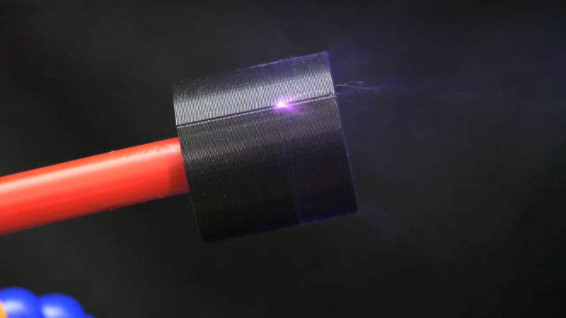
To make things a little more hands-off, [AT] added a pneumatically actuated switch to the supply, along with some indicator lights to help prevent him from leaving the supply powered up. He also reworked the low-voltage DC supply section, replacing a fixed-voltage supply and a DC-DC converter with a variable DC supply. This had the side benefit of providing a little bit more voltage to the ZVS driver, which goosed up the HV output a bit. The biggest change, though, was to the potted part of the HV section, which showed signs of arcing to the chassis. It turns out that even at 100% infill, 3D printed PLA isn’t a great choice for HV projects; more epoxy was the answer to that problem. Along with rewinding the primary on the flyback transformer, the power supply not only hit the 60-kV spec, but even went a little past that — and all without any of that pesky arcing.
We thought [Advanced Tinkering]’s first pass on this build was pretty slick, but we’re glad to see that it’s even better now. And we’re still keen to see how this supply will be put to use; honestly, the brief teaser at the end of the video wasn’t much help in guessing what it could be.


Aww i expected mehdi from electroboom. Like lessons never learned :-)
He should just dunk the whole HV section in purified mineral oil.
Industry standard right there…
Maybe, but the epoxy was supposed to be very highly insulating, and it’s not going to develop a leak or get air bubbles it didn’t start with, so it’s not all one sided.
I wonder how filament meant to be non conductive would do.
You get nylon filled with glass microspheres that is supposed to be a very good insulator as well as numerous other materials with the same claims.
Or what about an open infill, like gyroid and filling the part with sand or oil? It seems that should work too.
I know nothing about filament/printing but is it possible black filament is colored with carbon black?
Could be, would depend on brand what pigment they use, problem is PLA is mildly capacitive, shouldn’t use it for battery boxes let alone HV insulation
Instead of a flyback you can use the zvs to drive a tesla coil air core transformer, with proper resonant tuning, and submerge it in mineral oil
Problem with zvs is latching issues running over 70 volts input or so, maybe igbt or sicfet may fare better and not blow up, have to clamp gate voltages and iirc ain’t as easy as it seems
Typically you avoid black pigments due to carbon risks. Ive always used white 3D prints around HV and worked fine with 150KV. Opt not to use ZVS and just use a fullbridge of IGBTs and an inverter chip to set deadtime etc so everything runs 100% mint