When we last left [Wes] amidst the torn-open guts of his Logg Dogg logging robot, he had managed to revitalize the engine and dug into the hydraulics, but one big obstacle remained: the lack of the remote control unit. In today’s installment of the Logg Dogg series, [Wes] summarizes weeks of agony over creating a custom circuit based around a microcontroller, a joystick and a lot of relays and other bits and pieces to drive the solenoids inside the logging machine that control the hydraulics.
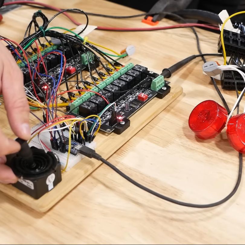
Most of the struggle was actually with the firmware, as it had to not only control the usual on/off solenoids, but also a number of proportional solenoid valves which control things like the track speed by varying the hydraulic flow to the final drives.
This requires a PWM signal, which [Wes] generated using two MOSFETs in a closed-feedback system, probably because open loop controls with multi-ton hydraulic machinery are not the kind of excitement most people look forward to.
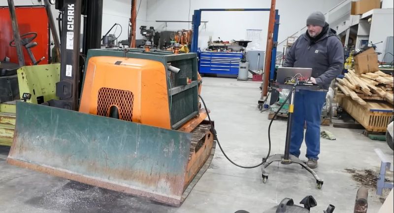
Ultimately he did get it sorted, and was able to take the Logg Dogg for its first walk since being rescued from a barn, which both parties seemed to rather enjoy. The background details of this machine and the project can be found in our first coverage.
We’re looking anxiously forward to the next episode, where the controller goes wireless and the sketchiness gets dialed down some more.


Needs a seat!
You wouldn’t want a seat on a device that’s made to bank on steep slopes and which handles multitonne logs by dragging on a steel cable. I see multiple ways this could get you killed. As wxplained in the video- a 12ft cable requred him to be too close for comfort.
It was probably designed to separate the operator from the skidder, but human occupied skidders were and probably still are the norm. So yes, but no.
I love this project. I wonder where Wes got the idea to “dither” the hydraulic solenoids? Is that common in proportional hydraulics or did he test it and realize that was needed?
Dither is a standard practice when quick response is required. It prevents the proportional valve from binding.
It’s pretty common in just about every proportional controller I’ve worked on. TBH I’ve never needed to adjust it but I’ve always had brand new valves to play with. Might be more of a thing on older more worn in gear.
His is probably not very worn, being a prototype, but the seals/shuttles may be degraded due to or fouled up. I would say they may not be worn in, but that would go counter to your experience.
Also, his closed loop most likely has measurement issues. For example, I didn’t hear anything about linear encoders, though I wasn’t listening very carefully. I thought he was measuring the current, i.e. the effort required to push the shuttle.
Maybe a bit more PID would help since he’s using relays (don’t remember where in the chain). Maybe the solenoid inductance is affecting the PWM signal. Perhaps it could even be the solenoid temperature. … Lots of potential calibration variables to consider.
now when it has 4m long control cable, it is almost as useful as logging horse :) not really, horse has follow me function, avoid obstacles and partial voice control :)
More Sketch-Bell