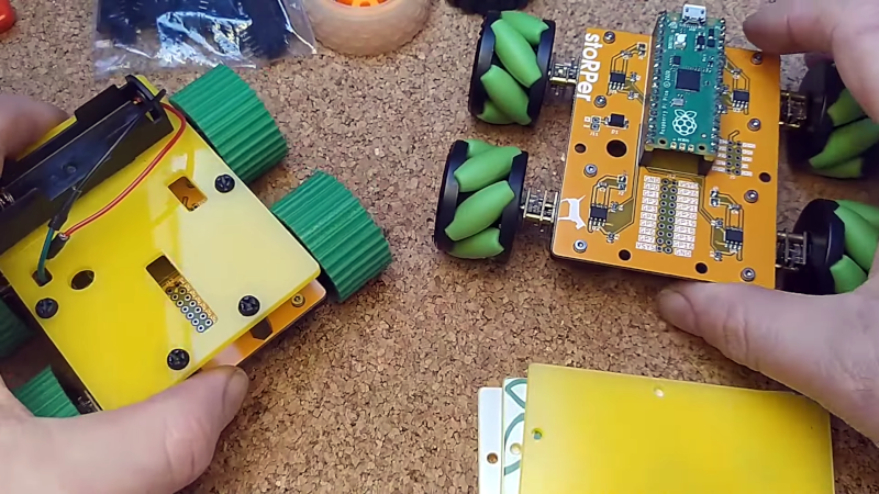
It is a fun project to build a simple robot but, often, the hardest part these days is creating the mechanical base. [Concrete Dog] has a new open source design for stoRPer that uses a PC board as the base. The board has a Raspberry Pi Pico and motor drivers. The modular design allows you to add to it easily and use custom wheels. The video below shows some treaded wheels and some mechanum wheels with gears.
There are mounting holes for sensors and also a way to put another deck above to hold other circuits, power, or whatever you like. There’s lots you could do with this as a starting point.
Some of the parts are 3D printed, like the motor mounts, for example. This offers some flexibility on motors. There are even files for printing PLA wheels with TPU treads that look like they would work well.
The idea is that with a 3D printer and the PC board, you should be able to build something easily. Obviously, you’ll need to find options for motors. Still, with a populated board, many other parts are printable or easy to repurpose. For example, the video mentions using repurposed vape batteries as a power source.
We were a little disappointed there was no video of the little robots doing anything, but if you’ve programmed these sorts of robots before, you know they can be a lot of fun and very capable, especially with a Pi Pico on board.
You could argue that you don’t need four wheels to do this. That does require strange wheels, though, and we bet the stoRPer will do better on terrain with the right wheels, too.


It’s a simple idea to use the PCB as part of the mechanical construction but there is a hidden problem with this. Ceramic parts such as MMLC capacitors and resistors are very brittle and break easily when the PCB is flexed, and this probably happens a lot when the PCB is used like this. This can be mitigated a lot by mounting the capacitors in a location where the PCB is not bent. For example directly between the two bolts for the motor bracket. The location of the motor driver is less critical because it’s legs have a bit of flex in them and they won’t break.
PCB flex? How much you think that weighs?
With this I doubt there is going to much flexing unless you add pounds of weight to the chassis and plan on speeding over non smooth terrain or through water… So, as a learning tool I think it is a great idea. Table tops, wood floors, etc.
The Pico has ‘plenty’ of processing power to handle almost anything you throw at it…. Even with using the overhead of Python for programming with Wifi connected. Cool beans!
Also, if still worried, it would not be that hard to cut a piece of plywood same size as the PCB, attach wheels to the plywood, thread the motor wires to four holes you cut in the plywood, and attach to PCB which is mounted on the plywood. Simple. Or if a 3D printer person, same idea but out of PLA. Lots of custom ideas for the platform if not satisfied with the kit itself.
Mmm… nah.
Too bulky.
How about this instead…
See the screws that mount the motors to the PCB?
Picture a rectangle (lines, not filled) drawn on the PCB such that it intersects each of those screws.
Move any components or jumpers intersecting that rectangle. Zooming in on the pic in the summary it looks like there is only one.
Now make a steel (if you can) or 3d printed plastic (more likely) rectangle (again, not filled) with screw holes that can be bolted on top of the PCB via the motor bolts to add stiffness.
For a more robust version you could even have crossbeams so long as they arch upwards enough to clear all the components on the board. Such cross beams could even have screw holes for mounting an upper deck.
But of course.. all this would be optional. Someone not worried about it could still build the PCB-only robot basically as-is, all that was changed was the location of a couple components.
Wait… better idea!!!
Keep all ceramic chips, super fine traces, etc… stuff that breaks easy from PCB flex bunched up in 4 particular areas of the PCB. Put them just inside from the motor screw holes. Or.. if you are definitely not going to make the supports I described above.. put the delicate components right over the motors.
This way the body of the motors (or brackets holding the motors on), anchored to two points on the PCB serves to prevent that spot from flexing!
If those are printed brackets… maybe even re-design them to have three anchor points in a triangle shape. Now you are protected from flexing across two axis.
Of course.. at that point.. if you are redesigning the motor mounts you could just connect them together into one solid mass…
Bro, It’s a toy robot…. It will be fine!
… Unless you add pounds of weight…
… Bro, it’s a toy robot…
Toys like this are very likely to be handled a bit rough. You accidentally drop it on the floor, or it drives full speed into a wall, or you hit it with your foot or sit on it (on the couch under a cushion) and such events are likely to cause enough flex in the PCB to break those ceramic parts. A lot of people do not realize how brittle these things are.
PCB’s are designed to be used inside enclosures, and those enclosures shield the PCB from all this sorts of mishaps. especially with toys like this, and the wheels that stick out and act as levers to transfer external forces to the PCB, it will get bent a lot.
Finding shorted MLCC’s on a PCB is no fun. Dave EEVblog also once had such a PCB. It was a 15A (20A?) SMPS power supply which had an MMLC close to the screw connectors for the output cables, and it broke just because of the flex in the PCB from the force of the screwdriver when the cables were mounted. Another very common way for PCB’s to get damaged in this way is by the “pizza cutter” wheels used to cut V-grooving. There are guidelines for how far to keep MLCC’s and resistors away from the V-groove (and for their orientation, which is also a factor).
And as Rclark mentioned. If you use some piece of plywood for the chassis itself (or the plastic plate used in the second half of the video) then the whole problem is avoided in the first place.
It isn’t that your points are not valid, it that you are waaaay over engineering what is essentially a demo board or a toy to play with. Of course it will break if you sit on it, the PCB is not even the most likely failure point. Sure why don’t we just use a heavy copper or aluminum IMS to increase rigidity? We can even heat-sink the drivers way better!
But we don’t need to tear into all the things that are wrong with this device when it’s not trying to solve the worlds the problems… Bro…
A learning tool or demo board is useless if it breaks within a few times of using it.
Beginners are likely to do things with it that it isn’t designed for. For example ramps, jumps, carrying loads, etc.
Even something as simple as seeing how steep a ramp it could go up often ends with it falling off the side.
Using a PCB as it’s main structure makes it fragile and difficult to replace, without replacing the whole PCB.
” or it drives full speed into a wall”
How fast is that with this thing? I’m not imagining speeds where that matters…
Daughter boards for any sensitive parts, attach to the main board via some through hole headers. But in my experience I’ve NEVER seen MLCCs fail from normal amounts of vibration or the stresses involved in screwing a board on to something else.
Pico is no joke for a ‘simple’ robot. Dual ARM Cortex M0, maybe even WiFi and BT, sounds pretty sweet.
Switch to through hole for more of the components, and maybe use the copper traces in a way that makes it stronger?
Ultimately you are going to move to another platform, as a learning tool to grasp the concepts this is probably 1/10 the price of comparable equipments.
“the hardest part these days is creating the mechanical base”
Realy? We have less than 200 dollars, and very capable, 3d printers nowadays.
Or cut a piece of plywood and drill a few holes ;)… then you don’t have to figure out how to use software ->then design -> 3D print.
When I was teaching a robotics course at Tokyo HackerSpace, I made base building part of the class. We modified servos for continuous rotation, so you get a motor, gearbox and bridge driver all in one. As for bases, I demoed with a plank of MDF and double sided tape. I made my “teacher’s bot” with styrene plastic and just pushed self tapping screws through. Student bases included: A smart phone cardboard box (these things are super sturdy cardstock), a 100 yen desk organizer basket, a bento lunch box, one guy went nuts with laser cut acrylic, and one kid ripped the wheels off an old toddler playschool type car. Making bases is “more fun” than programming the robot ;)
How about designing a PCB with through-hole components. It would even look retro.
Because assembly would be much more expensive (either money, or time if then having to assemble themselves).
Not if the through hole parts are not fitted by the pcb assembly house. Just do them yourself. 2 minute job.
Or/and have the pcb made thicker. 2.4mm wouldn’t cost a whole lot more.
Or, stop over thinking a probable non-problem.
And if it’s a learning exercise, learning to diagnose failed components is very valuable. I certainly learn a lot more from things that don’t work than those that do.
Using the PCB as the chassis in this case is a brilliant idea. Very nice indeed!
Here’s an even more barebones way to hack up a toy robot: just stick two servos and a battery to a breadboard: https://www.hackster.io/konstantint/breadboardbot-ec993d