When the job at hand is measuring something with micron-range precision, thoughts generally turn to a tool with a Mitutoyo or Starrett nameplate. But with a clever design and a little electronics know-how, it turns out you can 3D print a displacement sensor for measuring in the micron range for only about $10.
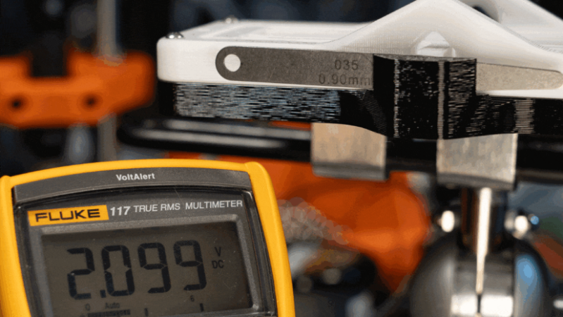
While the tool that [BubsBuilds] came up with isn’t as compact as a dial indicator and probably won’t win any industrial design awards, that doesn’t detract from its usefulness. And unlike a dial indicator — at least the analog type — this sensor outputs an easily digitized signal. That comes courtesy of a simple opto-interrupter sensor, which measures the position of a fine blade within its field of view. The blade is attached to a flexure that constrains its movement to a single plane; the other end of the flexure has a steel ball acting as a stylus. In use, any displacement of the stylus results in more or less light being received by the phototransistor in the opto-interrupter; the greater the deflection, the less light and the lower the current through the transistor. In addition to the sensor itself, [Bub] printed a calibration jig that allows precision gauge blocks or simple feeler gauges to be inserted in front of the stylus. The voltage across the emitter resistor for these known displacements is then used to create a calibration curve.
[Bub] says he’s getting 5-micron repeatability with careful calibration and multiple measurements of each gauge block, which seems pretty impressive to us. If you don’t need the digital output, this compliant mechanism dial indicator might be helpful too.
Thanks to [Bub]’s friend [Ethan] for the tip.


The optointerrupter should probably be shielded from room ambient light if you’re trying to get that sort of precision out of it.
I like.
The used sensor( EE-SX1070 according to the website (Digikey USD4) has a linear range of approximately 1mm (graph @ 02:48). With a 10 bit ADC (don’t now how useful better ADC is) this translates to a resolution of 0.1mm. Ambient light such as Scott mentioned above may be a factor in the lower measured resolution / accuracy, but also the simple 3D printed black piece of plastic. It is probably not flat, and bends easily under load. This sensor / flexure combination really begs for a better measurement setup to show what it can do.
Also, neither the video nor the datasheet has any suggestion of how diode current is digitized. I guess something better then a simple resistor to do a current to voltage conversion is warranted here.
Duh, typo. With 1mm and 10 bit ADC, resolution becomes 1um. (5 times better then measured accuracy).
Yes, resolution is not accuracy, but I guess there is room to get the accuracy closer to the resolution.
In addition, for accurate measurements you also have to keep the IR LED current constant. If you follow the “10 times better” paradigm as with his gauge blocks, that would translate to 0.01% deviation of LED current, which would be 0.5mV from the voltage source. Unless the same voltage source is used as a reference for the ADC. In that case the whole system turns into a quasi radiometric system.
As it is, the whole part about the gauge blocks is a bit absurdly out of context. If you want to reach that level of accuracy / linearity / etc, then you have to look at the whole system, and not just put a few resistors on a breadboard and call it good enough.
Don’t interpret this too badly. I like the idea, and I was surprised that these sensors have a decent lineairity over a 1mm range. This simple and cheap setup has lots of potential, but to really show off what it can do it does need more attention to details.
I’m glad this one got posted. I remember sending a link in via the tips line and I can’t believe I missed it!