Have you ever needed to hunt down a short circuit, but you’ve had no idea where it is or how it’s happening? As it turns out, there are tools to help in that regard. Enter the Leakseeker-89R.
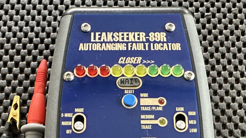
The device is able to help hunt down short circuits that measure anywhere from 0 to 300 ohms. The device is typically used with two leads on a given pair of traces, and it has a display made up of red, yellow and green LEDs. As the leads are moved closer or farther from the short circuit, the display changes to indicate if you’re getting hotter or colder. There’s also a third lead that can be used to allow testing under more challenging conditions when there is a large capacitance in-circuit with the traces you’re testing.
Fundamentally, it’s basically a very accurate resistance meter, finely honed for the purpose of hunting down short circuits. We’ve featured similar tools before. They can be of great use for troubleshooting. Meanwhile, if you’re building your own test tools in your home lab, don’t hesitate to let us know! We’re always dying for hot tips on the best DIY lab equipment for saving time, frustration, and money.


I use a thermal camera. Saved my day a few times
I don’t own a thermal camera, but spraying some isopropyl and seeing where it vaporizes first works well to find a shorted component
Where is the Arduino based Leakseeker DIY homebrew?
Would love an acoustic output where the resistance measurement changes frequency like in the tone ohm(?). That makes finding shorts much easier, because you can concentrate on the probing and don’t need to constantly look up to get the reading.
Especially useful in tight places or when you’re unsure wether you actually punctured the surface oxide or not.
This kit has just that. https://www.mercedelectronics.com/eds-89leakseekercompletekit.aspx
Bit Pricey, but worth every penny!
My unit is the EDS-89 plus battery and self test all packaged in a Hammond hand-held case.
Good idea!
Some refinements:
– Short probes for zero setting with a zero button.
– Set a ‘far’ point to get it into range with a separate button.
– When getting closer tone will increase up to 1khz or so meaning 0 ohm short
– When getting farther than the closest point recently measured do a low beep of 100hz or so. Hysteresis maybe 1-10% to prevent bad connection/oxydized/conformal coating?
– Use a synth chip/dac to play a note instead of a square wave beep :)
Or just use voltage injection and thermal imaging camera :)
The probe length doesn’t matter as the unit is self-calibrating.
The range window is automatically selected by the micro.
The tone will change up or down depending on your proximity to the short.
The range is 0 – 300R but the reading is always relative to the previous reading.
There is hysteresis built in. Probing a point longer than around a second will cause the unit to recalibrate the reading if necessary.
A synthesized beep can always be done (for more money) :)
I could include thermal imaging (for a lot more money) :)
It does have an acoustic output that changes tone based on your proximity to the short.
There is an acoustic output. It changes tone relative to the resistance reading up or down.
I took your “tone ohm[?]” bit as making a partial joke that while the tone frequency is altered, the “tone” would in fact be someone say “ohmmmm”, pitched up or down accordingly.
My first thought was that the leading “ohm” bit would need repeating instead of pitching a constant “mmmm” loop up/down based on the distance to the short. So naturally my 2nd thought was a slow to rapid repeating of a simply “ohm” sound file, pitched up/down as needed, for some added laughs [and annoyed bystanders].
“A very accurate resistance meter”. A ‘resistometer’? Oh, wait – an Ohmmeter.
Yeah…it’s a bit more sophisticated than an ohmmeter. It’s better described as a Computer controlled, auto-ranging, 0-300R relative reading Micro-ohmmeter with 16-bit DAC and audio-visual output. (Just rolls off the tongue…) :)
Yeah, probably would want to call it something else, For Short.
Just in case there was any doubt, the Leakseeker-89R is a relative-reading micro-ohmmeter. It automatically finds a match between the resistance seen at the probe tips and an internally generated value. It outputs both a visual display of LEDs and an audible tone that changes based on the proximity to the short. A microcontroller and 16-bit DAC automatically find the correct measurement window to use and will update as the user probes around the short.
Not to diminish this project, but there has been an off the shelf product for decade(s) that achieves the same result and for relatively low $ ($36.90 USD). I happen to find this device mentioned in an old electronics article and so I bought one… and have been extremely impressed at how well it works along with a ridiculously long battery life (years and years). So… if you do not want to DIY or need some of the functionality of this project… then check out the “Circuit Probe Model 105”:
https://probemaster.com/105-audible-continuity-probe/
Thanks Rog. It is an adaptation of the EDS-89 kit produced in the 1980’s. Sorry you are less than impressed. It is an aid to fault-finding. Buy it or don’t buy it – I don’t mind. If you want bare PCB’s to populate, I have those too…
No problem with it being a commercial thing. Just that the way the article was written was misleading, compounded with the meter appearing in a hackaday.io page.
They could have done a honest review, just pointing to where it was being sold, like when reviewing a new stm32 board from Aliexpress, or some other gadget.
I consider it useful, but won´t be buying it now, partly due to hard to find ( here ) components.
But it seems you got offended ( your “don´t mind” answer ). I´m not complaining about the product. Just the way the .io page was (wasn´t ) written. Just a text with the likes of “Hey guys, I built this meter, it does this and that, and I will be selling it on a, b & c ” would clear things up.
The hackaday.io page is still being completed. I think that’s the point of the page – a place to store bits of your project? It will be added to in due course. I didn’t know it would be published so soon. BTW I am not offended. “I don’t mind” was a flat statement. I really don’t mind.
My guess is Rog thinks your HaD-IO “project” is spam. I’d go further and say “not even interesting spam”
Even if you didn’t want to open source it you could keep your PIC code a secret and at least publish schematics so people could get an idea of what is going on. Instead you post some glamour shots of something that looks like a 1/4 century old Elektor kit with one of the IC names scrubbed off.
At least the Viagra spam I get in my hotmail inbox has blinky fonts to make it stand out.
Well Cunning Fellow, I am so glad you took the time to write your glowing report. It really doesn’t matter what your opinion of my project is. Every so often I will come across sad individuals like yourself who have to find fault with anything other people do. Obviously, you have a fixed opinion on just what I should publish on my page. I will not be able to please you so I won’t try.
Was it really necessary to smear my project with your snide remarks? Do you feeI morally superior now? Do you think you have successfully entertained the masses?
Look, I designed and built this. I am selling them. I haven’t fully completed my hackaday.io page yet. But, it seems that isn’t good enough for you.
I apologize for falling so far short of your obviously high standards. Perhaps next time you won’t be so quick to judge but I have a sneaking suspicion that won’t be the case…
It’s not just my opinion. It is a fact. In its current state it is spam.
You could please me. I am easy to please.
Make it un-spammy and I will apologise.
Include at least a schematic, a description of how the software works and that would be enough to make it not spam. I don’t care if it is closed source. I am not one of those people that demand everyone give away their trade secrets.
Three photos and a link to your ebay store is spam. That is un defendable position. Attack my character all you want. Won’t stop you from being a spammer.
As I have pointed out elsewhere on this page, I have not yet completed my hackaday.io page and I didn’t publish it on Hackaday. It was put there by Lewin Day who is, presumably, one of the editors.
Yes, I’m selling on ebay. Yes, that’s all that’s on the page at the moment. Yes, I am glad for the eyeballs on it.
I don’t really care what you choose to think of me. If you have no interest and believe it to be spam, that is your right. I will be posting more stuff to the project but on MY timetable NOT yours. I won’t be goaded into publishing stuff just because you think I should.
Just put this in your spam folder and move on…
Fantastic. Great. Complete it in your own time.
I am interested in short locators and continuity testers.
I have built a lot of them myself and have even made (nice and helpful) comments on HaD on other peoples designs.
You don’t need to take my advice. You might think I am a nasty horrible person. You might not even think you are a spammer. BUT I was not the first person to point out that it was lacking detail to be a “project”
I was just just responding to Rog who was the first person to say something. I am 100% sure Rog was not the first person to THINK it. He was just the first person to type it.
Sometimes the advice of people that you think are being mean to you is better than the advice of people that are heaping you with praise.
The Leakseeker-89R is, admittedly, a niche product. It has a single purpose but does that job extremely well. Just as there are many tools that can do a particular job, you will quickly find out that only a few of them do the job well.
2 words
GenRad BugHound
2 words
Different Principle
David, what is the test current and compliance voltage?
Can you please mention that in the specs. One place mentioned it will not damage 3.3V IC’s but I imagine people using this tool to troubleshoot graphics card shorts and they are quite low voltage IC’s.
I prefer many mA and a voltage below what will damage IC’s.
Modern multimeters are a wimpy 1mA and just under 3V. Brymen are even less current ~0.3mA and not good enough IMHO to punch through oxides and passivation layers.
Just bought a vintage DMM with 4mA test current, old Simpson 260’s could use 100mA (on 200 ohms range)- which made these legendary for use out in the field, outdoors, rain , dirt, rust, dealing with real-world wiring and connectors. Not a cozy lab bench.
Wish you the best in your project, it looks really useful.
Hi Kelly,
The Leekseaker-89R is a rework of the original EDS-89 from EDS inc. and was designed by Dave Miga. He gave me permission to do a rework of the PCB layout. I incorporated some additional stuff such as battery operation and sized it to fit a Hammond case. There is a test circuit built into the front panel. I didn’t design the circuit. That said, the output voltage is around 2.5v and current 8 – 16mA depending on the value of the short (0-300R).