When everything used wires, it was easy to splice them or replace them. Not so much with PC boards, but everyone has their favorite method for repairing a broken trace. [Mr. SolderFix] has his five favorite ways, as you can see in the video below.
Of course, before you can repair a trace, you probably have to expose it since most boards have solder mask now. Unless you plan to shut the trace at both ends, exposing the actual trace is probably the first step.
The first method is to just blob with solder, but we aren’t fans of that. Solder is not a great interconnect, so we nearly always put a small bit of wire over the gap, even if we might cover it with solder. That way, if the solder cracks over time, you still have a conductor as long as the solder bonds to the trace and wire. We did like that he used a blob of solder mask to cover the repair, which was a nice touch.
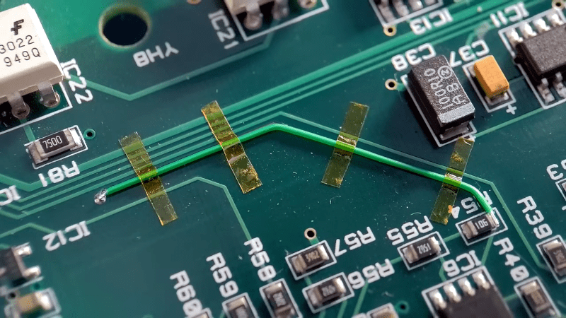
Of course, that isn’t going to work if you have a long delaminated trace. In particular, about two inches of a track was totally off the substrate. Here, using a wire is essential. We usually don’t bother to fit it exactly to the trace, but he is a bit more particular than we are. He used solder to model the bends in the wire and then straightened it out. That serves as a guide for how long to cut the jumper wire. He then bends the jumper to fit the trace and tacks it down with Kapton tape. It doesn’t work any better than one of our spaghetti-like repairs, but it does look better.
You’ve probably seen — or could deduce — how to do these repairs, but tips like using solder to model a trace are priceless. Some repairs have been done with copper sheets instead of wires. We didn’t see him using any conductive paint, which we’ve also had good luck with and we’ll admit we’ve covered repairs with clear nail polish rather than solder mask, but there are many possibilities, of course.
What’s your favorite method? It is harder — but not impossible — to repair boards that are completely broken. If you are a masochist, put your wires inside the board instead.


by far the easiest is enameled wire of the type that, as long you start at the end, can strip using solder
Depends what the break is, if it’s a cracked board (likely SRBP) then I flex the board slightly so the crack opens up a little and run some cyanoacrylate into it, once that’s cured I then bridge over broken traces with solid core wire.
If it’s mechanical damage to the traces only then I’ll bridge a cut trace with solder, if it’s a ripped up trace then Kynar solid core wire held in place with cyanoacrylate gel and activator or UV cure glue.
Haven’t tried UV cure soldermask yet, I just need an excuse to buy some.
Some 27 years ago my father accidentally dropped a TV set on the floor. The CRT survived, but the PCB broke in half. At TV repair shop they told us they don’t have replacement PCB and the cost of new one would be almost as much as the cost of the entire TV. At other repair shop an older fellow told us he can attempt the repair. He used DIP packages for alignment, glued halves with epoxy resin and strips of FR4 laminate, replaced broken resistors and then spent hours to carefully repair each broken trace with wire, the type leads are made of. After testing he used more epoxy to protect his repair. Few years later we gave away that TV, and as far as I can tell it worked until it was thrown away.
In 1997?
Eastern Europe?
1997, Poland. It was a big Thompson TV, barely two years old. Repair was worth it…
TV Repair shop? What’s than?
Used to be a thing in Poland years ago. It was basically, well, a place where they repair TVs.
Not only TVs. Radios, tape players, amps, VCRs, anything to do with home audio and video. Nowadays if it breaks, it gets thrown away, despite the fact that most repairs are super-easy…
You will not find such repair man now.
You can: the problem is that the relative costs of TVs have dropped precipitously but costs of labour have not, alongside modern TV PCBs being far more complex than a SD analog CRT’s PCB would be – have fun trying to successfully bodgewire a 160MHz differential bus trace run over a rigid-flex board!
When your TV was worth a few months wages, a few hours of someone’s wages to repair it made perfect sense. When a new TV is so cheap that a few hours wages would cover its cost twice over, then repair is difficult to justify.
Even on environmental grounds the answer is not clear-cut once you start adding in all the externalities of a bespoke repair (single-person transportation to and from the repair shot because you can’t fit your 75″ TV on the bus, fraction of the fully-burdened costs of operation of operating a single-person shop, etc).
Average income in Poland in 1995 was ~702zł per month. Average cost of good TV was 1500-2000zł. Now average income per month is more than 5968zł. Good TV costs 2000-2500zł for decent size.
The repair was 200zł, which was tough for us, because the very next day my father had a minor stroke and spent two weeks in the hospital. He was actually taking the TV to the repair shop, when that happened. TV spent those two week inside our car, parked on the next street from our apartment block…
In my neighborhood, on the first night there would have been ghetto diamonds on the street and no TV in the car.
The most likely failure in a modern TV is going to be a bad electrolytic capacitor in the power supply. Anyone with basic soldering skills can replace one. The big electrolytics are usually still through hole. The hardest part is getting the case open. Just be careful and remember to unplug it and discharge the power supply input capacitors before working on it.
If you’ve got spare scrap PCBs (who doesn’t), you can always rip the trace off another board to use it as a replacement, too.
I like to use the clipped leads off resistors and caps to make short splices for traces.
I have a spool of such wire, 0.6mm diameter. Very useful, for example to add extensions for clipping probes. It can also be used for making jumpers, board repairs and for reinforcing power traces…
WHY does it need repair in the first place? In my experience, a thin trace may overheat from too much current, or it may suffer physical damage from a foreign object. Neither of those have I seen very often. More common is pads lifting off while trying to replace a stubborn component or even more common, trying to remove/re-attach a wire– which acts as a heatsink and you struggle to get just the right amount of heat to remove/attach it and melt the solder without collateral damage.
I’ve seen many.
Depends what field your in to.
I’ve done a lot of PCB repairs for people trying to mod their equipment with zero soldering experience other than a couple of youtube videos.
I’ve seen and repaired stuff which looks like someone has gone at it with a mig welder.
We sometimes use solderwick, especially if it’s a higher current trace that’s vaporized, and hot glue to stick stuff down with. But it’s really nice to have an array of bare wire of different sizes for fine work. For a while we were designing a lot of QFN package parts and when those blew up, having to replace both a trace and an under-the-chip pad was a real hassle, so fine wire was a huge help. (For that, superglue is a better choice than hotglue because it’ll most likely survive soldering the chip down without going all gooey.)
I’ve done a lot of trace repair, including burnt inner layers and planes. Much of the time, I’ve pulled copper from scrap boards and soldered it into place and used epoxy to rebuild the layers. Blue wire or enameled wire can go on the top layers if the current is low enough but sometimes those get the scrap board copper as well.
My biggest problem has been in filling scraped out burnt board areas and bonding copper with an adhesive that is both strong enough to hold up long term and to also withstand the heat of (usually low temp) soldering. High temp epoxies are my current solution, but even they will melt during soldering. I’m betting some HAD person has a good solutions that I haven’t come across.
Those who repair Original Xbox consoles will be very familiar with this fix. Early revision motherboards are notorious for trace rot, generally because they fell victim to the capacitor plague.
This is just an excuse for bodge skill porn and I’m here for it 🌻🤓🦾
I’m impressed with the precision of the person’s hand movement. All his moves were superbly precise, no hand shaking, evey tool placement was done exactly at the right place and for the right amount of time. The video was heavily magnified so in reality the tool movents was just a fractions of a millimeter, so difficult to do, even harder when filming. Wow, what a skill. Bravo!