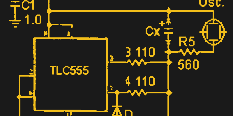
[Peter Demchenko] wanted to use a low power TS555 in an ESR meter design. The problem is, he needed to handle significant current sink requirements for cases where the capacitor under test had a low ESR. The TS555 wasn’t up to the task.
However, [Peter] made an interesting observation. the output pin of the device can sink or source current. However, the discharge pin is exactly the same output but can only sink current.
But what if you tied them together? Using some equalizing resistors, that’s exactly what he did, and this roughly doubles the rated current sink capability. According to [Peter], you do make the circuit more sensitive to power supply variations, but that could be an acceptable trade, depending on your application.
The meter schematic confused us for a moment because the R3 and R4 designations are corrupted. Both the equalizing resistors, it appears, are 110 ohms. The schematic legend should read “R3 110” not “3 110.” The same for R4 which appears as “4 110.”
We do love unusual ways to use a 555. If you need to read ESR, and you have one of those ubiquitous component testers handy, they will give you a reading of ESR, among other things.


No mention of the actual test current and 12V is a lot for compliance voltage, no in-circuit testing for this meter. Many ESR meters use a transformer to achieve high test-current and diode-clamp for low pulse voltage.
I use Bob Parker’s Blue ESR meter, it outputs 50mA on the highest (lowest ESR) range and works on batteries too measuring their ESR. All I need in the lab.
I bought Bob’s (Alltronics) ESR meter back in the 1990s.
It was a small marvel at the time! It is still on the equipment shelf.
ESR meter page
https://zilogbob.com/esr_meter/esrmeter.htm
The ts version can source 50ma and sink 10 the bog standard can sink lime 200
Is it really a hack to use the wrong part for the designed application?
Output stage of the bipolar ones are janky and not suited for “precise” applications.
They’re however excellent drivers for something like relay coils or similar.
If you want precision, your only option is the CMOS based ones, but their pin 3 & 7 ain’t able to handle as much current.
Can’t we just use one of those $0.10 mcus, and a buffer transistor? Aren’t the days of the 555 finally almost over yet? Plus, in this case, using an MCU could also power a display like an OLED or something to really make the ESR meter a self-contained unit.
There’s beauty in a design that can be described as “works when assembled, no programming required”.
Besides, there’s also the “but where’s the fun in that?…” factor.